
A centrifugal filter device

A technology of centrifugal filtration and filter instrument, applied in centrifuges and other directions, can solve problems such as inability to fully separate large particles of impurities

Inactive Publication Date: 2017-06-27
朱思龙
View PDF8 Cites 0 Cited by
  • Summary
  • Abstract
  • Description
  • Claims
  • Application Information

AI Technical Summary

Problems solved by technology

[0004] The present application provides a centrifugal filter device, which solves the technical problem of not being able to fully separate large particles of impurities in the prior art

Method used


Image

  • A centrifugal filter device
  • A centrifugal filter device
  • A centrifugal filter device

Examples


Embodiment Construction

[0047] In order to better understand the above-mentioned technical solution, the above-mentioned technical solution will be described in detail below in conjunction with the accompanying drawings and specific implementation methods.

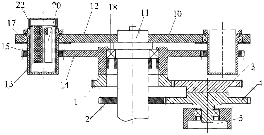
[0048] figure 1 It is a structural schematic diagram of a centrifugal filter device in a preferred embodiment of the present application. like figure 1 As shown, the centrifugal filter device includes a centrifugal filter instrument 10 and a centrifugal filter sample bottle 20 fixed on the centrifugal filter instrument 10 .

[0049] First, the centrifugal filter 10 is introduced, and the centrifugal filter 10 includes a drive shaft 11, a sample turntable 12, a bottle carrier 13, a transmission gear 14, an autorotation gear 15 and a speed regulating device.

[0050] The drive shaft 11 is driven to rotate by a motor. The sample turntable 12 is fixed on the drive shaft 11 . When the driving shaft 11 rotates, the sample turntable 12 rotates with ...


PUM


Abstract

The invention discloses a centrifugal filter device. The centrifugal filter device includes a centrifugal filter and a centrifugal filter sample bottle. The centrifugal filter includes: a drive shaft; a sample turntable fixed on the drive shaft; a bottle carrier arranged on the on the sample turntable and can rotate relative to the sample turntable; the transmission gear is arranged on the drive shaft and can rotate relative to the drive shaft; the rotation gear is fixed on the bottle carrier and is connected to the bottle carrier The transmission gear meshes; the speed regulating device is arranged on the transmission gear; by fixing the centrifugal filter sample bottle on the centrifugal filter instrument, the centrifugal filter sample bottle is driven to rotate and Revolution, so that the suspension can interact with the filter membrane and the membrane cavity to fully separate the particles of different diameters, the large particles are left in the membrane cavity, and the filtration process is completed, which solves the problem that cannot be fully achieved in the prior art. Technical problems of separating large particles of impurities.

Description

technical field [0001] The invention relates to the technical field of filtering equipment, in particular to a centrifugal filtering device. Background technique [0002] In the prior art, the conventional method for separating cohesive particles with different diameters in the suspension is: select a filter with a suitable mesh size, stir repeatedly, immerse in the liquid repeatedly and filter repeatedly. [0003] However, in the laboratory, due to the small amount of samples to be separated and the requirement to prevent cross-contamination, it is not suitable to use conventional filtration methods for filtration. In order to prevent the filter mesh from being clogged, the experimenter usually chooses a filter with a larger aperture than the target particle. Filters with a much larger diameter filter directly one by one. This filtration method cannot fully separate the large particle impurities in the liquid, and it is time-consuming and labor-intensive. Contents of the...

Claims


Application Information

Patent Timeline
Patent Type & Authority Patents(China)
IPC IPC(8): B04B5/00B04B7/00B04B9/08B04B9/10B04B9/02
Inventor 朱思龙
Owner 朱思龙
Learn More