
Special support tool for ship T-shaped bar

A technology for profiles and ships, which is applied in the direction of berth, dry dock, transportation and packaging, etc., can solve the problems of unfavorable welding deformation, easily damaged steel, and substandard precision, and achieve the effects of saving manpower, accurate installation and positioning, and convenient support

Inactive Publication Date: 2015-05-06
JIANGSU DAJIN HEAVY IND
View PDF0 Cites 2 Cited by
  • Summary
  • Abstract
  • Description
  • Claims
  • Application Information

AI Technical Summary

Problems solved by technology

[0004] 1) Welding temporary supports will produce a lot of telltale signs and require a lot of auxiliary process materials
[0005] 2) The horse foot treatment process after welding is very easy to damage the base metal of the section steel
[0006] 3) Most of the temporary supports are usually arranged on one side of the profile, which is not conducive to the control of welding deformation, resulting in substandard precision

Method used


Image

  • Special support tool for ship T-shaped bar
  • Special support tool for ship T-shaped bar
  • Special support tool for ship T-shaped bar

Examples


Embodiment 1

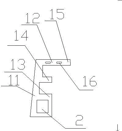
[0020] As shown in the figure, a special support tool for ship T-shaped bar, including two plates 1, the plates 1 are arranged opposite to each other, connected into one body by bolts or other fasteners, the plates 1 are integral components, The panel 1 comprises a side plate 11, an upper end plate 12, a lower end plate 13 and a middle plate 14, the upper end plate 12, the lower end plate 13 and the middle plate 14 are distributed parallel to each other, and are all vertically connected to the side plate 11 to form a E-shaped member, the end of the upper end plate 12 is provided with a mounting plate 15 extending horizontally outwards, the mounting plate 15 is provided with mounting holes 16, the number of mounting holes is not limited, it can be 2 or more , the mounting holes are arranged in the horizontal direction, and the lower end plate 13 is provided with a square through hole 2; the outer surface of the side plate 11 is a slope, and an angle α is formed between the outer...

Embodiment 2

[0022] As shown in the figure, a special support tool for ship T-shaped bar, including two plates 1, the plates 1 are arranged opposite to each other, connected into one body by bolts or other fasteners, the plates 1 are integral components, The panel 1 comprises a side plate 11, an upper end plate 12, a lower end plate 13 and a middle plate 14, the upper end plate 12, the lower end plate 13 and the middle plate 14 are distributed parallel to each other, and are all vertically connected to the side plate 11 to form a E-shaped member, the end of the upper end plate 12 is provided with a mounting plate 15 extending horizontally outwards, the mounting plate 15 is provided with mounting holes 16, the number of mounting holes is not limited, it can be 2 or more , the mounting holes are arranged in the horizontal direction, and the lower end plate 13 is provided with a square through hole 2; the outer surface of the side plate 11 is a slope, and an angle α is formed between the outer...


PUM


Abstract

The invention discloses a special support tool for a ship T-shaped bar. The special support tool comprises two plate members, wherein the plate members are oppositely arranged, and are connected into a whole by virtue of a fastening member, the plate members are integral members, the plate members comprise side plates, upper end plates, lower end plates and middle plates, wherein the upper end plates, the lower end plates and the middle plates are all vertically connected with the side plates to form E-shaped members, mounting plates which outwards horizontally extend are arranged at end heads of the upper end plates, mounting holes are formed in the mounting plates; square through holes are formed in the lower end plates; the outer side surfaces of the side plates are inclined surfaces, and included angles alpha are formed between the outer side surfaces of the side plates and the lower end plates, and are 84 DEG. Compared with the prior art, the special support tool has the characteristics of being accurate in positioning and convenient to mount. By using the special support tool, procedures of welding and grinding can be removed, so that excessive procedures are avoided, and thus the production time and cost are saved.

Description

technical field [0001] The invention relates to a support device, in particular to a special support device for T-shaped materials such as large cabin ribs in ship sections, and belongs to the technical field of ship processing tooling. Background technique [0002] With the advancement of science and technology, the pace of modern shipbuilding is getting faster and faster, and the requirements for shipbuilding precision are getting higher and higher. In order to adapt to better and faster development, ensuring the accuracy of segmented production, shortening the production cycle, and reducing the cost of production have become an important link that cannot be ignored. [0003] In the traditional segmented production process, temporary welding support is used for the assembly and positioning of profiles to prevent welding deformation. From the perspective of process flow, there are mainly two defects in the following aspects: [0004] 1) Welding temporary supports will prod...

Claims


Application Information

Patent Timeline
IPC IPC(8): B63C5/02
Inventor 杭友斌王友军张军张晓军雷志刚石亚飞姚福来
Owner JIANGSU DAJIN HEAVY IND
Learn More