Implanted direct relief valve

A direct-acting overflow valve and valve seat technology, which is applied in fluid pressure actuating devices, servo motor components, mechanical equipment, etc., can solve the problems of large installation structure, loose pressure regulating screw, unreasonable structure setting, etc. Achieve the effects of avoiding volume changes, improving stability, and ensuring positional accuracy

Active Publication Date: 2015-05-06
宁波中意液压马达有限公司
View PDF6 Cites 2 Cited by
  • Summary
  • Abstract
  • Description
  • Claims
  • Application Information

AI Technical Summary

Problems solved by technology

The direct-acting relief valve needs to be installed inside the hydraulic valve block or hydraulic actuator when in use. The direct-acting relief valves currently on the market usually appear in the form of cartridge valves, that is, the direct-acting relief valve is used as An independent combined component is installed inside the hydraulic valve block or hydraulic actuator, so the disadvantage is that the entire installation structure is large in size and cannot be adapted to compact structures, resulting in greater limitations in use
In addition, in order to adjust the pressure of the direct-acting relief valve, a pressure regulating scre...

Method used


Image

  • Implanted direct relief valve

Examples


Embodiment Construction

[0014] The present invention will be further described below in conjunction with the accompanying drawings.

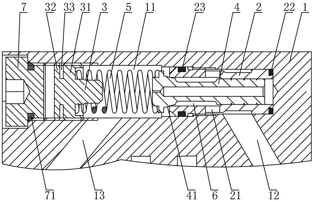
[0015] Such as figure 1 The implanted direct-acting relief valve shown includes a valve block 1, the valve block 1 is provided with a mounting hole 11 along the axial direction, and the valve block 1 is respectively provided with an oil inlet 12 and an oil outlet communicating with the mounting hole 11 Port 13, a safety valve is set in the installation hole 11, the safety valve includes a valve seat 2 and a pressure adjusting screw 3, a valve core 4 is movable in the valve seat 2, and one end of the valve core 4 protrudes from the outside of the valve seat 2, the valve A spring 5 is provided between the protruding end of the core 4 and the pressure adjusting screw 3, a pressure chamber 6 is formed between the valve seat 2 and the valve core 4, and a valve for connecting the pressure chamber 6 and the oil inlet 12 is provided on the valve seat 2. The oil hole 21, the p...


PUM


Abstract

The invention discloses an implanted direct relief valve. The implanted direct relief valve comprises a valve block, wherein an installation hole is formed in the valve block, an oil inlet and an oil outlet are formed in the valve block, a safety valve is arranged in the installation hole and comprises a valve seat and a pressure adjusting screw, a valve element is arranged in the valve seat, one end of the valve element stretches out of the valve seat, a spring is arranged between the stretching-out end of the valve element and the pressure adjusting screw, a pressure cavity is formed between the valve seat and the valve element, an oil hole used for enabling the pressure cavity to be communicated with the oil inlet is formed in the valve seat, a conical surface matched with the valve seat is arranged on the stretching-out end of the valve element, an internal thread section is arranged on the inner wall of the valve block, a first thread section and a second thread section matched with the internal thread section are arranged on the pressure adjusting screw in parallel, an axial gap is reserved between the first thread section and the second thread section, and the leading-in angle of the first thread section is different from that of the second thread section. The implanted direct relief valve is simple and reasonable in structure, small in size, high in installation speed and good in self-locking effect.

Description

technical field [0001] The invention relates to the technical field of direct-acting overflow valves, in particular to an implanted direct-acting overflow valve. Background technique [0002] The relief valve is a hydraulic pressure control valve, which mainly plays the role of constant pressure relief in hydraulic equipment. There are many types of relief valves, and the direct-acting relief valve is one of them, which is well known and common to the public. The direct-acting relief valve needs to be installed inside the hydraulic valve block or hydraulic actuator when in use. The direct-acting relief valves currently on the market usually appear in the form of cartridge valves, that is, the direct-acting relief valve is used as An independent combined component is installed inside the hydraulic valve block or hydraulic actuator. The disadvantage of this is that the entire installation structure is large in size and cannot be adapted to compact structures, resulting in rel...

Claims


Application Information

Patent Timeline
IPC IPC(8): F15B13/02
CPCF15B13/02
Inventor 罗超群曹磊林双海
Owner 宁波中意液压马达有限公司
Why Eureka
Try Eureka