Device and method for realizing automatic detection of bandwidth of cavity filter

A cavity filter and automatic detection technology, which is applied in the direction of measuring devices, instruments, and measuring electrical variables, etc., can solve the problems of increased base station complexity, low reliability and accuracy, and reduced reliability, so as to reduce complexity , to achieve the effect of simplicity and reliability

Inactive Publication Date: 2011-03-23
ZTE CORP
View PDF0 Cites 0 Cited by
  • Summary
  • Abstract
  • Description
  • Claims
  • Application Information

AI Technical Summary

Problems solved by technology

However, since spectrum is a very scarce resource in various countries, there is a problem that spectrum resources may be dynamically allocated within a certain period of time. In order to support different spectrums, RRU needs to replace its key module cavity filter on site. device
[0003] However, the problem caused by the replacement of the cavity filter is that the RRU cannot automatically obtain the hardware information of the new cavity filter, because the cavity filter is a passive structural part, and generally only communicates with the new cavity filter through the radio frequency interface. The power amplifier module of the front stage is connected to the antenna of the rear stage, and there is no other interface. After manually replacing the cavity filter on site, it is necessary to manually write this information into the RRU through the external interface of the RRU, or the cavity filter is equipped with a Interfaces other than radio frequency, or obtain changes in the shape of the cavity filter by means of photoelectric detection
However, these methods of obtaining information must require manual intervention or provide an additional interface for the cavity filter; or, after replacement, the shape of the cavity filter is different from that of other frequency bands, and manual intervention It will lead to low reliability and accuracy, increasing the interface or changing the size will increase the complexity of the base station and reduce the reliability

Method used


Image

  • Device and method for realizing automatic detection of bandwidth of cavity filter
  • Device and method for realizing automatic detection of bandwidth of cavity filter
  • Device and method for realizing automatic detection of bandwidth of cavity filter

Examples


Embodiment Construction

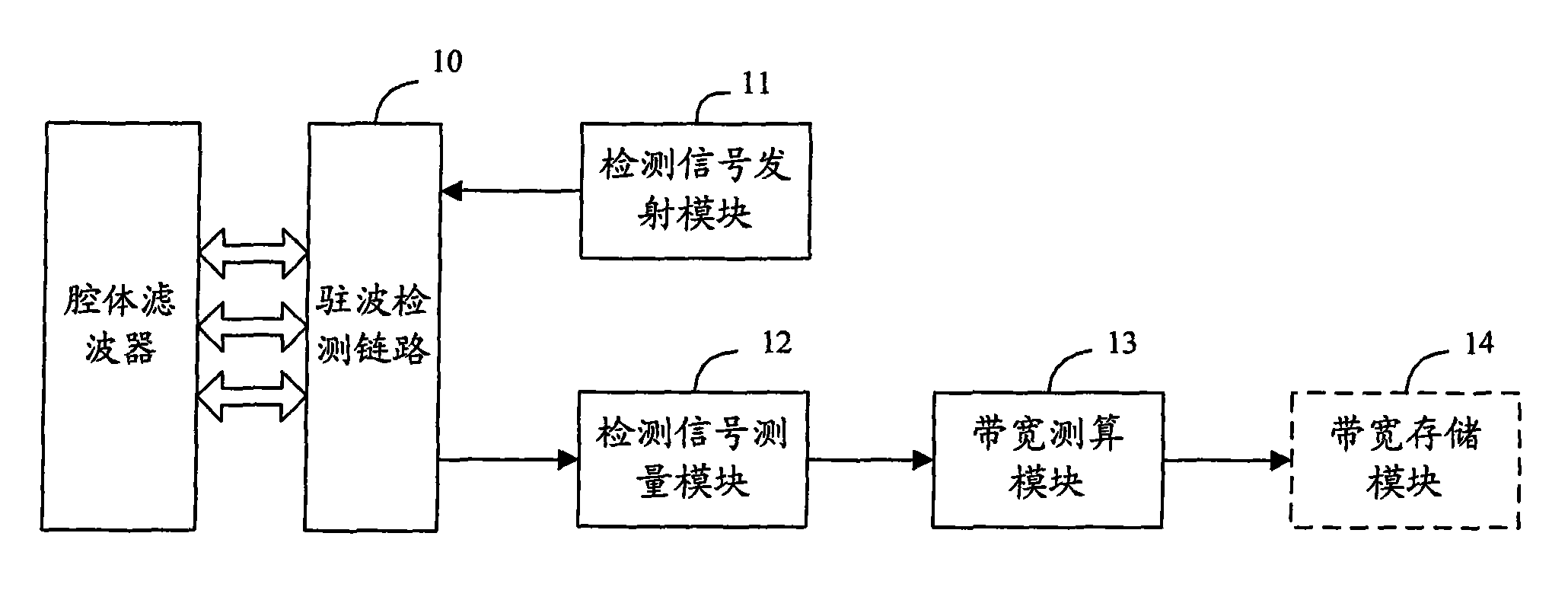
[0026] Since the cavity filter of the RRU is connected to the load, the standing wave in the passband is good, but the standing wave outside the passband will deteriorate sharply. In this case, standing wave detection will occur. Correspondingly, the chain of standing wave detection in the RRU The circuit will emit a detection signal to detect the standing wave. Usually, the antenna is the load of the cavity filter in practical applications.

[0027] The standing wave detection link in the RRU described herein is the prior art, and will not be repeated here.
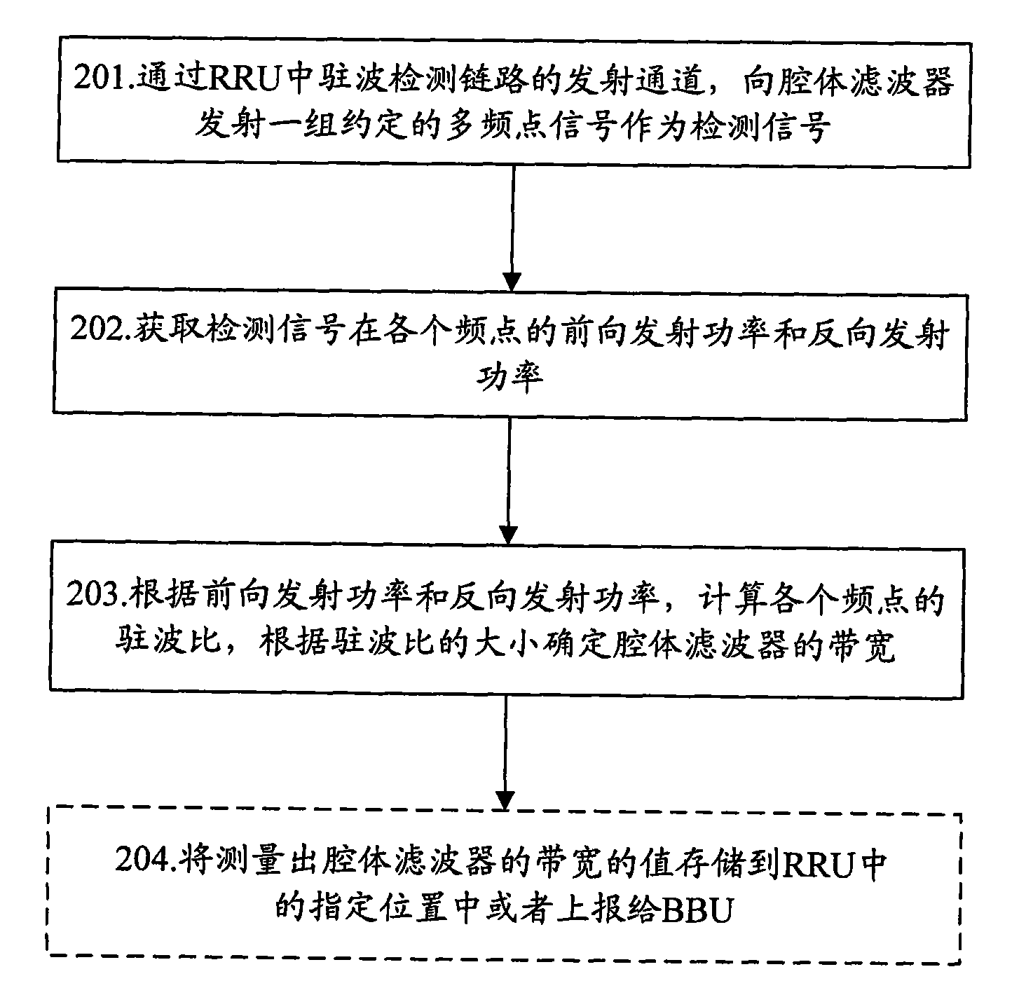
[0028] The basic idea of ​​the present invention is: use the standing wave detection link in the RRU to transmit the detection signal, measure the standing wave ratio of the detection signal at each frequency point, and then use the measured standing wave ratio to calculate and obtain the cavity filter device bandwidth.

[0029] Here, the frequency range of the detection signal exceeds the bandwidth of the cavity filte...


PUM


Abstract

The invention discloses a device for realizing the automatic detection of the bandwidth of a cavity filter. A detection signal is transmitted by utilizing a standing-wave detection link inside a radio remote unit and the standing-wave ratios of the detection signal on various frequency points are measured and then the bandwidth of the cavity filter is calculated and acquired by utilizing the standing-wave ratios obtained through measurement. The invention also discloses a method for realizing the automatic detection of the bandwidth of the cavity filter. The invention can be used for realizing the automatic detection of the bandwidth of the cavity filter almost without increasing cost or changing the boundary dimensions of the cavity filter at different frequency ranges or increasing additional digital interfaces; and in addition, the invention can ensure that the reliability is enhanced due to the automatic detection and is easy and convenient to realize.

Description

technical field [0001] The invention relates to the field of cavity filters, in particular to a device and method for automatically detecting the bandwidth of a cavity filter. Background technique [0002] In the current communication system, the separated base station has been widely used in the form of a baseband processing unit (BBU) and a remote radio unit (RRU). It is composed of a cavity filter for interference signals and a low-noise amplifier power amplifier subsystem. However, since spectrum is a very scarce resource in various countries, there is a problem that spectrum resources may be dynamically allocated within a certain period of time. In order to support different spectrums, RRU needs to replace its key module cavity filter on site. device. [0003] However, the problem caused by the replacement of the cavity filter is that the RRU cannot automatically obtain the hardware information of the new cavity filter, because the cavity filter is a passive structura...

Claims


Application Information

Patent Timeline
Patent Type & Authority Applications(China)
IPC IPC(8): G01R27/06
Inventor 杜媛媛
Owner ZTE CORP
Why Eureka
Try Eureka