
an air supply device

A technology of air supply device and air supply port, which is applied in space heating and ventilation details, household heating, noise suppression, etc., and can solve the problem of drainage, incomplete diversion, easy turbulence of flow field, and unsmooth air duct section Slippery and other problems, to achieve good comfort, less flow field disorder, and less air volume loss

Active Publication Date: 2018-03-30
AUX AIR CONDITIONING LTD BY SHARE LTD
View PDF6 Cites 0 Cited by
  • Summary
  • Abstract
  • Description
  • Claims
  • Application Information

AI Technical Summary

Problems solved by technology

Since this selection method directly blocks the tuyere, the flow field near the tuyere in the air duct is prone to disorder, vortices, and noise problems;
[0005] 3. On the other hand, if the air guide plate is used to block the air outlet, if it is not tight, it will affect the noise of the air duct, and because the shielding part does not form a whole with the air duct, the cross section of the air duct is not smooth, and at the same time it is affected by the vortex, resulting in drainage, The diversion is not complete, it is easy to cause the loss of air volume

Method used


Image

  • an air supply device
  • an air supply device
  • an air supply device

Examples


Embodiment

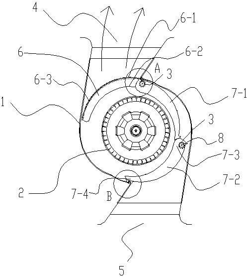
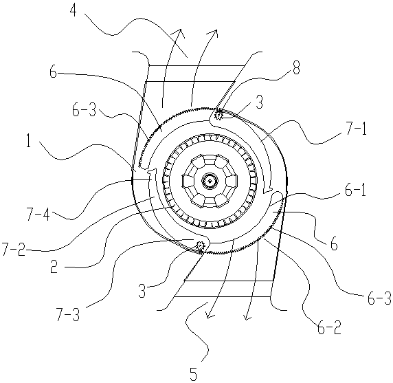
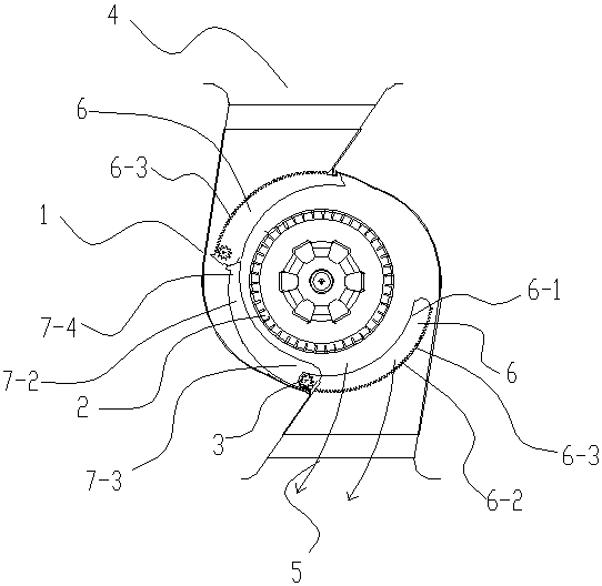
[0034] Embodiment: the air supply device of the present embodiment is as figure 1 , 2 , 3, 4, 5, 6, including the air supply housing 1, the centrifugal fan 2 installed in the air supply housing 1, the centrifugal fan 2 is connected with the matching fan blade drive motor, the air supply housing 1 is equipped with a wind deflector and a position adjustment drive mechanism. The air supply housing 1 is provided with an air supply port and a limit structure matching the wind deflector. The wind deflector is matched with the position adjustment drive mechanism. The wind deflector passes through the position Adjust the driving mechanism to move along the periphery of the centrifugal fan blade 2 to prevent the centrifugal fan blade 2 from blowing air to the air outlet. Of course, the fan blades can also be axial flow fan blades.

[0035] The position adjustment drive mechanism includes a gear 3 and a tooth track 6-3 meshing with the gear 3. The gear 3 is installed on the windshiel...


PUM


Abstract

The invention discloses an air supplying device. The air supplying device comprises an air supplying shell body and a fan blade arranged inside the air supplying shell body, an air supplying outlet is formed in the air supplying shell body, a barge board and a limit structure matched with the barge board are arranged inside the air supplying shell body, and the barge board moves along the periphery of the fan blade to prevent the centrifugal blade from discharging air to the air supplying outlet. The air supplying device has the advantages of being simple in structure, stable in operation, and good in whole-machine comfort. According to the air supplying device, a flow field disturbance is not easily to be generated inside an air flue, noise is low, and the loss of the air volume is small.

Description

technical field [0001] The invention belongs to air supply components, in particular to an air supply device for air conditioners. Background technique [0002] At present, there are air conditioners with similar structures on the market, especially air conditioners with multiple air outlets. When the air conditioner is working, each air outlet has air outlets. Generally, the distribution of the air outlets of existing air conditioners on the market is roughly as follows: up and down air outlets, left and right and down air outlets, four-sided air outlets, etc., but there is no function that can choose to control a certain air outlet to not let the air out. A few problems with traditional methods: [0003] 1. The traditional air outlet structure basically does not have a baffle structure, and it is not possible to choose to close the air outlet in one or more directions. The comfort of the whole machine in this way is not very good, and it cannot better meet the realizatio...

Claims


Application Information

Patent Timeline
Patent Type & Authority Patents(China)
IPC IPC(8): F24F13/10F24F13/24
CPCF24F13/10F24F13/24F24F2013/247
Inventor 古汤汤吴庆壮黄家柏
Owner AUX AIR CONDITIONING LTD BY SHARE LTD
Learn More