
A touch panel, a touch display device and a method for manufacturing the touch panel

A technology of a touch panel and a manufacturing method, which are applied in the field of touch panels, can solve the problems that the frame part of the touch panel is difficult to achieve a narrow frame effect, and it is difficult to achieve a narrow frame effect, so as to reduce the total width of the signal line, improve the Narrow border effect, the effect of overcoming limitations

Active Publication Date: 2018-02-06
WUHAN TIANMA MICRO ELECTRONICS CO LTD +1
View PDF3 Cites 0 Cited by
  • Summary
  • Abstract
  • Description
  • Claims
  • Application Information

AI Technical Summary

Problems solved by technology

Among them, the frame portion of the cover glass plate and the frame portion of the OLED display panel have enough space to realize the narrow frame design, while the frame portion of the touch panel is mainly composed of signal lines, due to the line width of the signal line The limitation of the line spacing leads to the limitation of the narrow frame design of the total width of the signal line. Therefore, it is difficult for the frame part of the touch panel to have a good narrow frame effect
[0004] To sum up, in the prior art, there is a limitation in the narrow frame design of the total width of the signal lines in the peripheral wiring area of ​​the touch panel, resulting in a small space for narrow frame design in the frame part of the touch panel, which is difficult to realize Technical Issues for Better Narrow Bezel Effects

Method used


Image

  • A touch panel, a touch display device and a method for manufacturing the touch panel
  • A touch panel, a touch display device and a method for manufacturing the touch panel
  • A touch panel, a touch display device and a method for manufacturing the touch panel

Examples


Embodiment Construction

[0036] In order to make the purpose, technical solutions and advantages of the present invention clearer, the present invention will be further described in detail below in conjunction with the accompanying drawings. Obviously, the described embodiments are only some of the embodiments of the present invention, rather than all of them. Based on the design concepts of the embodiments of the present invention, all other embodiments obtained by persons of ordinary skill in the art through equivalent replacement or other means without creative work shall also fall within the protection scope of the present invention.

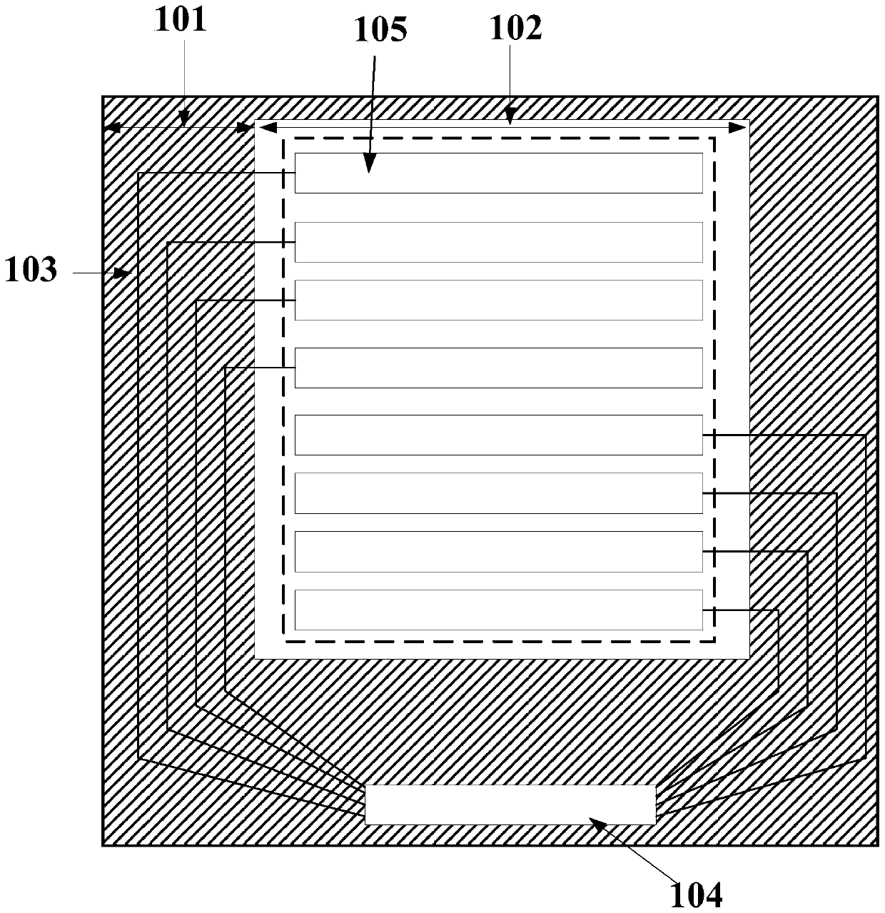
[0037] In general, touch panels such as Figure 1a As shown, it includes a touch substrate, a display area 102 on the touch substrate, and a wiring area 101 surrounding the display area. The display area 102 on the touch substrate is provided with a touch electrode 105, wherein the touch electrode 105 is a transparent conductive electrode, such as an ITO electrode. ...


PUM


Abstract

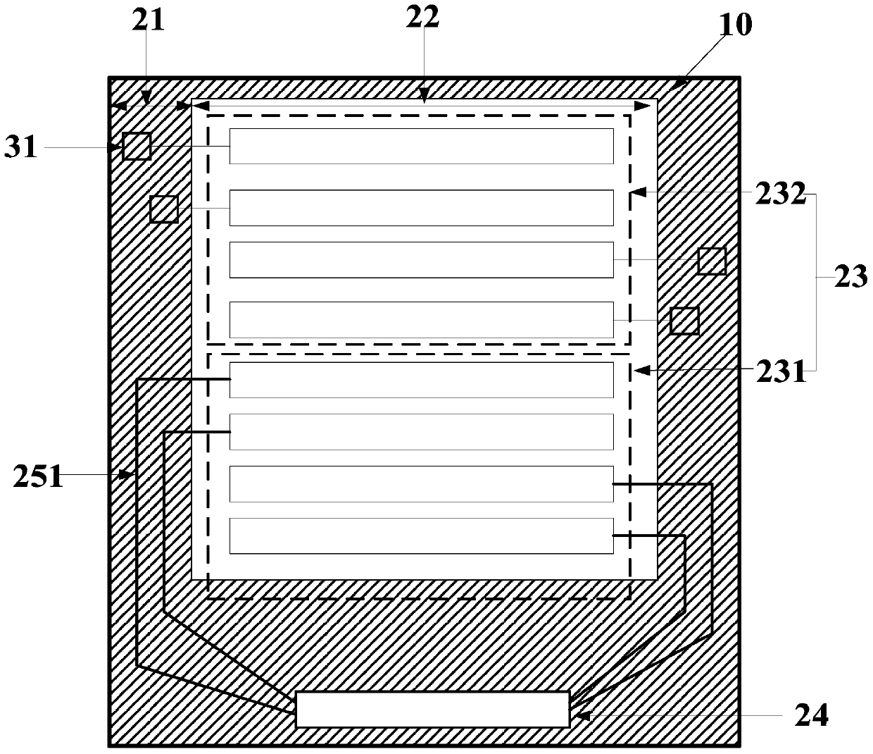
The invention discloses a touch panel, a touch display device and a manufacturing method of the touch panel. The touch panel includes a first substrate, a first conductive layer, a touch electrode, a second substrate and a second conductive layer, and is located on a display panel. The touch electrodes in the area include first touch electrodes and second touch electrodes; the wiring area of ​​the touch panel has signal lines for transmitting touch signals, including at least one first signal line and at least one second signal line , the first signal line is electrically connected to the first conductive layer, and the first signal line is electrically connected to the first touch electrode, the second signal line is electrically connected to the second conductive layer, and the second signal line is electrically connected to the second touch electrode Electrically connected, and the projections of the first signal line and the second signal line arranged on the same side of the touch panel in the vertical direction of the first substrate at least partially overlap, greatly reducing the total width of the signal line in the peripheral wiring area of ​​the touch panel , to achieve a better narrow border effect.

Description

technical field [0001] The present invention relates to the field of display technology, in particular to a touch panel, a touch display device and a method for manufacturing the touch panel. Background technique [0002] At present, the development trend of the touch display industry is developing toward narrow bezels. The design of narrow bezels can increase the size of the display area of ​​the display screen and bring better visual aesthetics to users. [0003] For the AMOLED (Active Matrix Organic Light Emitting Diode, active matrix organic light emitting diode) display screen with integrated touch function, the frame effect consists of the frame part (visible area VA and ink area) of the cover glass plate Cover lens, the touch area The frame part (peripheral wiring area) of the control panel and the frame part (peripheral circuit and packaging area) of the OLED display panel are determined. Among them, the frame portion of the cover glass plate and the frame portion o...

Claims


Application Information

Patent Timeline
Patent Type & Authority Patents(China)
IPC IPC(8): G06F3/041
Inventor 熊志勇魏云燕
Owner WUHAN TIANMA MICRO ELECTRONICS CO LTD
Learn More