Method and device for determining candidate touch point

A touch point, touch area technology, applied in the input/output process of data processing, instruments, electrical digital data processing and other directions, can solve the problem of ghost removal and misjudgment.

Active Publication Date: 2015-05-06
HISENSE COMML DISPLAY CO LTD
View PDF5 Cites 8 Cited by
  • Summary
  • Abstract
  • Description
  • Claims
  • Application Information

AI Technical Summary

Problems solved by technology

[0004] Embodiments of the present invention provide a method and device for determining candidate touch points, which are used to solve the technical prob

Method used


Image

  • Method and device for determining candidate touch point
  • Method and device for determining candidate touch point
  • Method and device for determining candidate touch point

Examples


Example Embodiment

[0020] Example one

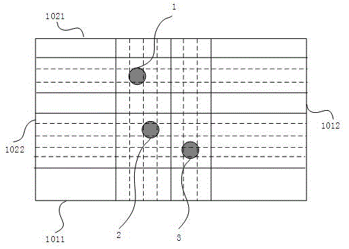
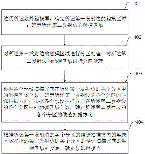
[0021] Figure 4 This is a flowchart corresponding to a method for determining candidate touch points provided in Embodiment 1 of the present invention Figure , The method is applied to an infrared touch screen. The hardware configuration of the infrared touch screen is consistent with the prior art. The infrared touch screen includes a first transmitting side 1011, a first receiving side 1021 corresponding to the first transmitting side 1011, Two transmitting sides 1012, a second receiving side 1022 corresponding to the second transmitting side 1012, the first transmitting side 1011 and the second transmitting side 1012 are provided with infrared emitting elements, the first receiving side 1021 and The second receiving side 1022 is provided with an infrared receiving element, and all of the In the picture , The dashed line between the frame formed by the transmitting edge (the first transmitting edge 1011 and the second transmitting edge 1012) and the recei...

Example Embodiment

[0044] Example two

[0045] figure 1 1 is a schematic diagram of a device for determining candidate touch points provided in Embodiment 2 of the present invention Figure , The device is applied to an infrared touch screen, the infrared touch screen includes a first transmitting side, a first receiving side corresponding to the first transmitting side, a second transmitting side, and a second receiving side corresponding to the second transmitting side , The first transmitting side and the second transmitting side are provided with infrared emitting elements, and the first receiving side and the second receiving side are provided with infrared receiving elements, the device includes:

[0046] The touch area determining module 1201 is configured to traverse the infrared touch screen to determine the touch area of ​​the first emitting edge; determine the touch area of ​​the second emitting edge;

[0047] The partition module 1202 is configured to perform partition processing on the tou...


PUM


Abstract

The embodiment of the invention provides a method for determining a candidate touch point. The method comprises the following steps of performing zoning processing on each touch area of a first emitting side after traversing an infrared touch screen, and performing zoning processing on each touch area of a second emitting side; determining a candidate scanning direction of each zone of the first emitting side and a candidate scanning direction of each zone of the second emitting side, further improving distinction degree of each candidate touch point; determining the candidate touch points according to intersection of the touch area in the candidate scanning direction of each zone of the first emitting side and the touch area of the candidate scanning direction of each zone of the second emitting side, thereby effectively improving the distinction degree of the candidate touch points and positioning precision of the touch points. The finally obtained candidate touch points are similar to the practical touch points, so that misjudgment is unlikely to produce in a ghost point removing process.

Description

technical field [0001] The present invention relates to the field of touch display, in particular to a method and device for determining candidate touch points. Background technique [0002] A touch screen is an electronic system that can detect the presence and location of a touch within the display area. Among the current touch technologies, infrared touch technology has the advantages of strong environmental adaptability, long life, and more identifiable touch points. like figure 1 As shown, it is a schematic diagram of the structure of the infrared touch screen. The appearance of the infrared touch screen is a rectangular structure, which consists of a long transmitting side 1011 , a long receiving side 1021 , a short transmitting side 1012 , and a short receiving side 1022 . There are several infrared emitting elements on the long transmitting side 1011 and the short transmitting side 1012 , and there are correspondingly several infrared receiving elements on the long...

Claims


Application Information

Patent Timeline
IPC IPC(8): G06F3/042G06F3/0484
Inventor 王武军
Owner HISENSE COMML DISPLAY CO LTD
Why Eureka
Try Eureka