A method and device for determining candidate touch points

A touch point, touch area technology, applied in the input/output process of data processing, instruments, electrical digital data processing and other directions, can solve the problems of inability to distinguish between multiple points, low multi-point positioning resolution, and low point accuracy.

Active Publication Date: 2017-11-10
HISENSE COMML DISPLAY CO LTD
View PDF6 Cites 0 Cited by
  • Summary
  • Abstract
  • Description
  • Claims
  • Application Information

AI Technical Summary

Problems solved by technology

[0004] Embodiments of the present invention provide a method and device for determining candidate touch points, which are used to solve the problem that the calculation of candidate touch points in the prior art only uses the optical path in the forward scanning direction. The optical path cannot distinguish between multiple points, leading to technical problems such as low resolution and low point accuracy in multi-point positioning

Method used


Image

  • A method and device for determining candidate touch points
  • A method and device for determining candidate touch points
  • A method and device for determining candidate touch points

Examples


Embodiment 1

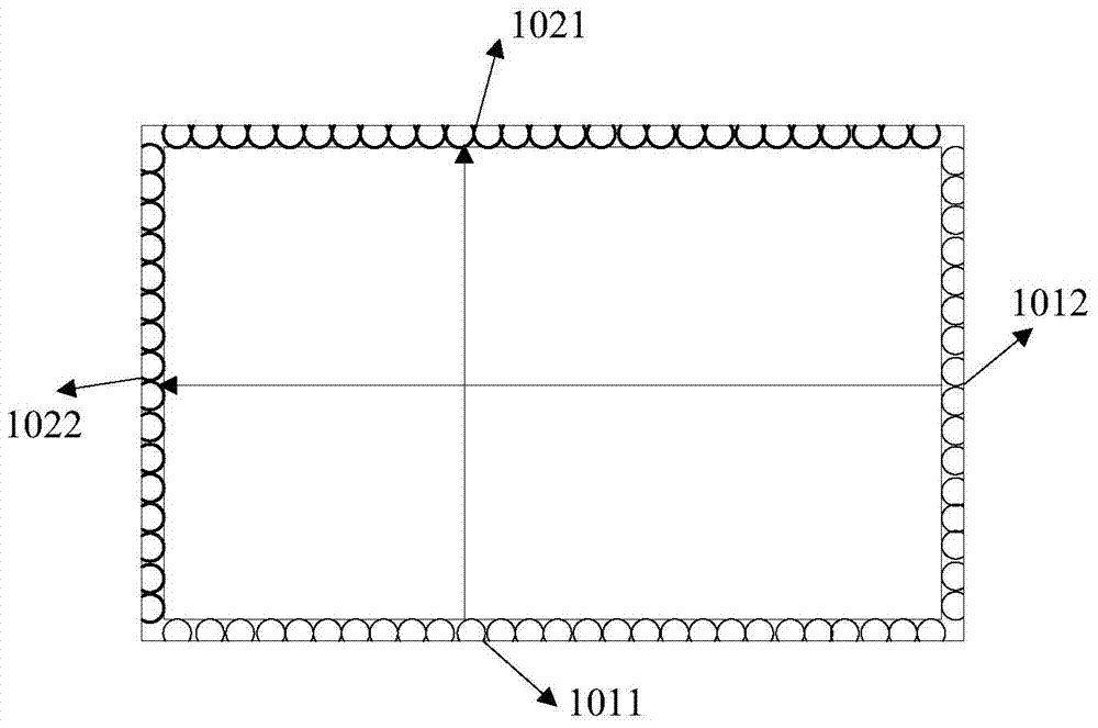
[0034] Figure 4 It is a schematic flowchart corresponding to a method for determining a candidate touch point provided by Embodiment 1 of the present invention. The method is applied to an infrared touch screen, and the infrared touch screen includes a first emitting edge and a first emitting edge corresponding to the first emitting edge. The receiving side, the second transmitting side, the second receiving side corresponding to the second transmitting side, the first transmitting side and the second transmitting side are provided with infrared emitting elements, the first receiving side and the described The second receiving side is provided with an infrared receiving element, and the method includes steps 401 to 404:

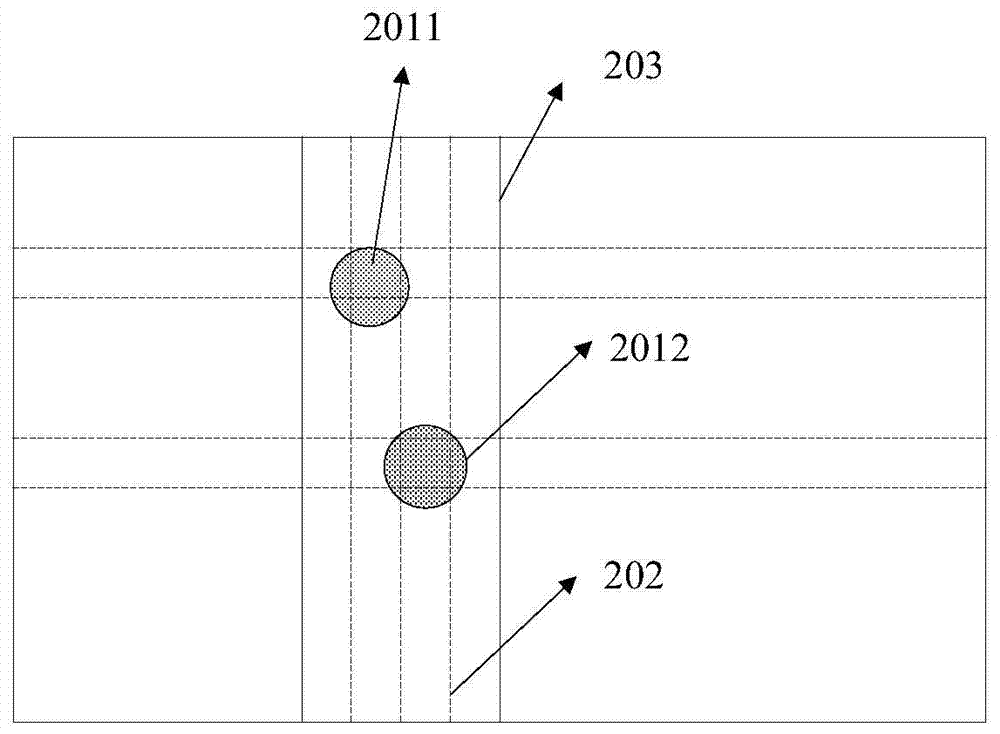
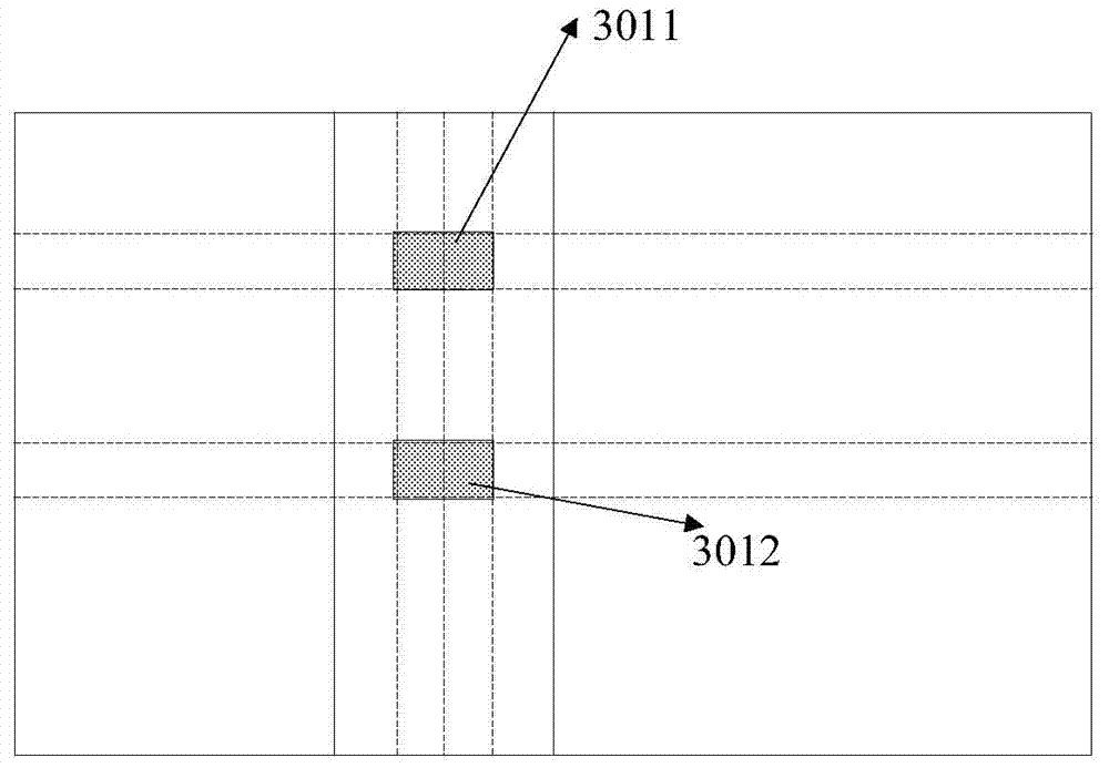
[0035] Step 401, according to the number of touch areas in each scanning direction of the first emitting side, determine the candidate scanning direction of the first emitting side; according to the number of touch areas in each scanning direction of the sec...

Embodiment 2

[0057] Figure 12 It is a schematic diagram of a device for determining candidate touch points provided by Embodiment 2 of the present invention. The device is applied to an infrared touch screen, and the infrared touch screen includes a first emitting edge and a first receiving edge corresponding to the first emitting edge. Two transmitting sides, a second receiving side corresponding to the second transmitting side, the first transmitting side and the second transmitting side are provided with infrared emitting elements, the first receiving side and the second receiving side Equipped with an infrared receiving element, the device includes:

[0058] The determining candidate scanning direction module 1201 is configured to determine the candidate scanning direction of the first emitting side according to the number of touch areas in each scanning direction of the first emitting side; The number of touch areas, to determine the candidate scanning direction of the second emitti...


PUM


Abstract

The embodiment of the present invention discloses a method and device for determining candidate touch points. The embodiment of the present invention first determines the candidate scanning directions of the first emission side and the second emission side, so that each touch point can be distinguished to the greatest extent; Each touch area of ​​the candidate scanning direction of the first emission side is partitioned, and each touch area of ​​the candidate scanning direction of the second emission side is partitioned; and by determining the candidate scanning direction of each partition of the first emission side and the second Candidate scanning directions of each subregion of the emission side to further improve the discrimination between each touch point; and then according to the touch area of ​​the candidate scanning direction of each subregion of the first emission side and each subregion of the second emission side Candidate touch points are determined by the intersection of the touch areas of the candidate scanning directions, which effectively improves the discrimination of multiple touch points and the positioning accuracy of the touch points.

Description

technical field [0001] The present invention relates to the field of touch display, in particular to a method and device for determining candidate touch points. Background technique [0002] A touch screen is an electronic system that can detect the presence and location of a touch within the display area. Among the current touch technologies, infrared touch technology has the advantages of strong environmental adaptability, long life, and more identifiable touch points. Such as figure 1 As shown, it is a schematic diagram of the structure of the infrared touch screen. The appearance of the infrared touch screen is a rectangular structure, which consists of a long transmitting side 1011 , a long receiving side 1021 , a short transmitting side 1012 , and a short receiving side 1022 . There are several infrared emitting elements on the long transmitting side 1011 and the short transmitting side 1012 , and there are correspondingly several infrared receiving elements on the l...

Claims


Application Information

Patent Timeline
Patent Type & Authority Patents(China)
IPC IPC(8): G06F3/042
Inventor 王武军
Owner HISENSE COMML DISPLAY CO LTD
Why Eureka
Try Eureka