A visual inspection system and method for fault identification of air-conditioning condensation pipe nozzle

A visual inspection and fault identification technology, applied in measuring devices, instruments, etc., can solve the problems of large-scale production of nozzle quality defects that cannot be detected in time, complex production site conditions, and low detection efficiency, so as to improve the efficiency of fault detection. and accuracy, convenient for timely processing, and high detection stability.

Active Publication Date: 2020-10-30
HUAZHONG UNIV OF SCI & TECH
View PDF6 Cites 0 Cited by
  • Summary
  • Abstract
  • Description
  • Claims
  • Application Information

AI Technical Summary

Problems solved by technology

[0003] In production, workers generally use random inspection to inspect the quality of nozzles. The detection method uses vernier calipers for size measurement and visual inspection of nozzle shape characteristics, but the reliability of manual inspection is low. mm-7.0mm, due to the soft texture of the copper tube, the manual measurement error is ±0.2mm, the measurement error is large, the nozzle is small and the number is large, and it is easy to miss it by visual inspection
Moreover, the conventional sampling inspection methods cannot detect the large-scale occurrence of nozzle quality defects caused by individual expansion head and expansion rod failures in time.
In the field of condenser nozzle inspection, due to the wide variety of products, the large number of single condenser nozzles, and the complicated production site conditions, most of them use manual inspection methods, which have low detection efficiency and often miss inspections

Method used


Image

  • A visual inspection system and method for fault identification of air-conditioning condensation pipe nozzle
  • A visual inspection system and method for fault identification of air-conditioning condensation pipe nozzle
  • A visual inspection system and method for fault identification of air-conditioning condensation pipe nozzle

Examples


Embodiment Construction

[0043] In order to make the object, technical solution and advantages of the present invention clearer, the present invention will be further described in detail below in conjunction with the accompanying drawings and embodiments. It should be understood that the specific embodiments described here are only used to explain the present invention, not to limit the present invention. In addition, the technical features involved in the various embodiments of the present invention described below can be combined with each other as long as they do not constitute a conflict with each other.

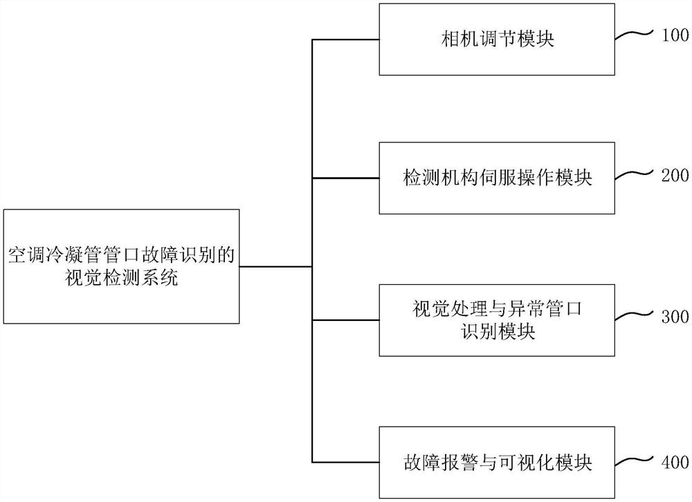
[0044] Such as figure 1 As shown, the embodiment of the present invention provides a visual inspection system for identifying the nozzle failure of the air-conditioning condensation pipe, which mainly includes a camera adjustment module 100, a detection mechanism servo operation module 200, a visual processing and abnormal nozzle identification module 300 and a fault alarm with visualization mo...


PUM


Abstract

The invention belongs to the field of intelligent detection and in particular discloses a visual inspection system used for pipe orifice fault recognition of an air conditioner condenser pipe. The visual inspection system disclosed by the invention comprises a camera adjusting module, a detection mechanism servo operation module, a visual processing and abnormal pipe orifice recognition module anda fault alarm and visualization module, the camera adjusting module comprises a portal frame and a CCD camera arranged on the portal frame, the detection mechanism servo operation module comprises acamera parameter setting unit and a portal frame motion parameter setting unit, the visual processing and abnormal pipe orifice recognition module comprises a pipe orifice diameter threshold value setting unit, a pipe orifice burst feature detection unit and a pipe orifice diameter detection unit. The invention also discloses a corresponding method. The visual inspection system disclosed by the invention realizes intelligent recognition on pipe orifice features and pipe orifice size of a condenser pipe, performs fault alarm and is higher in detection precision, higher in detection speed and high in detection stability, and production efficiency can be greatly improved.

Description

technical field [0001] The invention belongs to the field of intelligent detection, and more specifically relates to a visual detection system and method for fault identification of an air-conditioning condensation pipe nozzle. Background technique [0002] In the expansion tube production process of the condenser tube in the air-conditioning industry, the quality problem of the expanded tube is mainly due to the weak consistency of the expansion hole size of the condenser tube nozzle. In order to obtain a more detailed situation of the quality problems of the expansion tubes, multiple samplings are generally taken to count the quality problems of the expansion tubes, and the problems of unqualified nozzle size and expansion cracks of the condenser tube are particularly prominent. A finned tube heat exchanger generally contains dozens or hundreds of copper tubes, and if more than three tubes fail, secondary processing or scrapping is required. [0003] In production, worker...

Claims


Application Information

Patent Timeline
Patent Type & Authority Patents(China)
IPC IPC(8): G01D21/02
Inventor 朱海平马雷博张聪关辉何非
Owner HUAZHONG UNIV OF SCI & TECH
Why Eureka
Try Eureka