Positioning method for high-precision machining of thin-walled workpiece

A technology for processing thin-walled parts and thin-walled parts, which is applied in the field of high-precision machining and positioning of thin-walled parts, and can solve the problems of weak strength, deformation of thin-walled parts, and unsatisfactory circularity of thin-walled parts, so as to reduce the use of Longevity and the effect of preventing excessive sliding distance

Active Publication Date: 2015-05-13
CHONGQING MACHINE TOOL GROUP
View PDF10 Cites 7 Cited by
  • Summary
  • Abstract
  • Description
  • Claims
  • Application Information

AI Technical Summary

Problems solved by technology

However, the processing of thin-walled parts is more difficult, because thin-walled parts have poor rigidity and weak strength, and are easily deformed during processing, which makes it difficult to ensure the processing quality of parts.
[0003] At present, when the machining industry processes thin-walled parts, it usually roughs the inner hole first, and then uses spring steel expansion sleeves to fix the inner hole of the thin-walled part, and then processes the outer circle of the thin-walled part. The degree is guaranteed to be within 0.01mm. However, after the processing is completed, when the thin-walled part is not removed from the spring steel expansion sleeve, the outer roundness of the thin-walled part is detected to meet the processing requirements, but after the thin-walled part is removed from the spring steel expansion sleeve , t

Method used


Image

  • Positioning method for high-precision machining of thin-walled workpiece
  • Positioning method for high-precision machining of thin-walled workpiece
  • Positioning method for high-precision machining of thin-walled workpiece

Examples


Embodiment 1

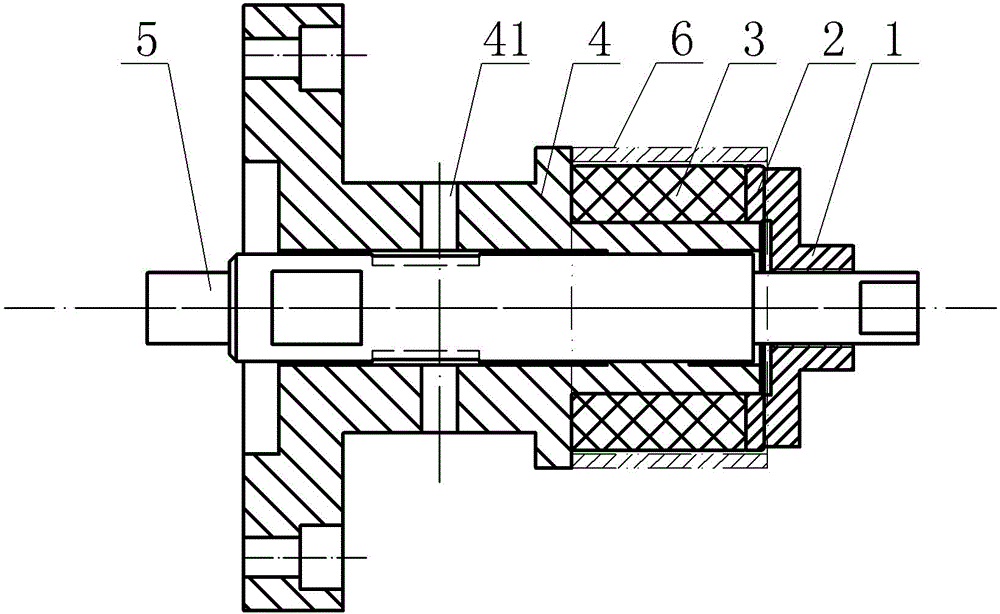
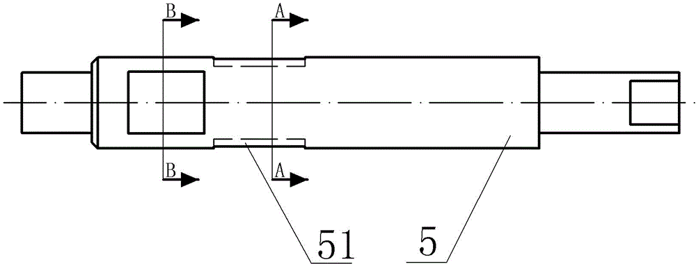
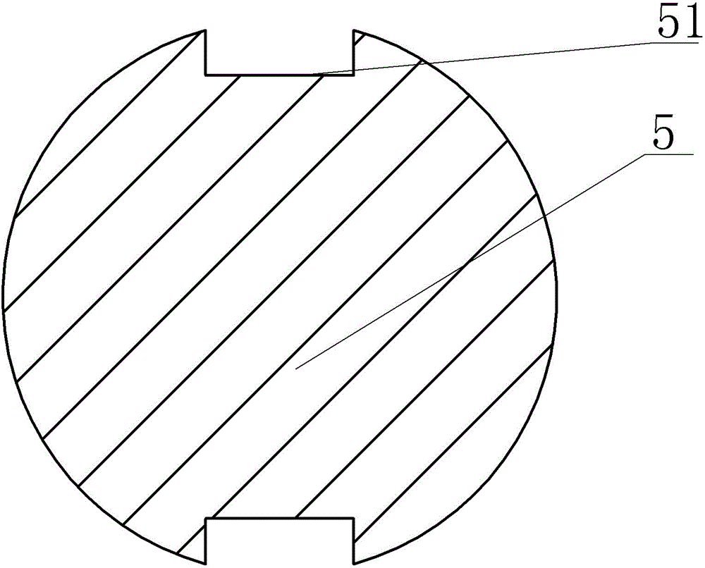
[0037] Embodiment one is basically as Figure 1 to Figure 7 Shown: a fixture tooling for thin-walled parts processing, including a rotating disk fixed on a lathe, a mandrel 4 and a tie rod 5 passing through the center of the mandrel 4, and hinged hole bolts between the mandrel 4 and the rotating disk connection, the reaming hole bolts can be subjected to shear force to ensure that the mandrel 4 rotates with the rotating disk, and the reaming hole bolts have high precision at the same time, which improves the processing accuracy of the thin-walled part 6. The mandrel 4 is also provided with a threaded adjustment hole 41, and the thread A screw is connected to the adjustment hole 41, and a groove 51 is provided at the corresponding position on the tie rod 5. Turn the screw to push it against the groove 51 of the pull rod 5, so as not to affect the sliding of the pull rod 5, so as to prevent the pull rod 5 from rotating and rubbing polyurethane. The wall of the inner hole of the ...

Embodiment 2

[0041] The difference from the first embodiment is that the interference fit between the inner hole of the polyurethane expansion sleeve 3 and the tie rod 5 is 0.2 mm, and the gap between the outer circle of the polyurethane expansion sleeve 3 and the inner hole of the thin-walled part 6 is 0.2 mm.

Embodiment 3

[0043] A positioning method for high-precision machining of thin-walled parts, comprising the following steps:

[0044] A. Blanking: The material is polyurethane rods, and according to the size of the thin-walled parts, a machining allowance is left for blanking to form an expanded sleeve blank;

[0045] B, processing polyurethane expansion sleeve: turning the expansion sleeve blank obtained in step A to form polyurethane expansion sleeve;

[0046] C. Clamping: Assemble and install the thin-walled parts outside the polyurethane expansion sleeve, and turn the shoulder nut to lock the thin-walled parts.

[0047] The spring steel expansion sleeve processing steps in the prior art are as follows:

[0048] 1. Heat treatment T235, then rough turn the right end face, addendum round turn to φ76mm, drill hole φ25mm, turn hole φ28mm, turn 20° taper hole with allowance of 0.7mm, get rid of gas; U-turn turn left end face fixed length, turn outer circle φ62mm Leave a margin of 0.7mm; nee...


PUM

PropertyMeasurementUnit
Sizeaaaaaaaaaa

Abstract

The invention discloses a positioning method for high-precision machining of a thin-walled workpiece. The method comprises the steps of A, blanking, wherein blanking is conducted by reserving machining allowance according to the size of the thin-walled workpiece by means of a polyurethane bar, and then an expanding sleeve blank is formed; B, machining of a polyurethane expanding sleeve, wherein the expanding sleeve blank obtained from the step A is turned to form the polyurethane expanding sleeve; C, clamping, wherein the thin-walled workpiece is assembled outside the polyurethane expanding sleeve, a flanged nut is rotated, and then the thin-walled workpiece is locked. According to the method, operation is easy, and convenience and practicality are high.

Description

technical field [0001] The invention relates to a lathe fixture, in particular to a positioning method for high-precision machining of thin-walled parts. Background technique [0002] Thin-walled parts have been increasingly widely used in various industrial sectors because of their light weight, material saving, and compact structure. However, the processing of thin-walled parts is more difficult, because the thin-walled parts have poor rigidity and weak strength, and are easily deformed during processing, which makes it difficult to guarantee the processing quality of parts. [0003] At present, when the machining industry processes thin-walled parts, it usually roughs the inner hole first, and then uses spring steel expansion sleeves to fix the inner hole of the thin-walled part, and then processes the outer circle of the thin-walled part. The degree is guaranteed to be within 0.01mm. However, after the processing is completed, when the thin-walled part is not removed fr...

Claims


Application Information

Patent Timeline
IPC IPC(8): B23B31/40
CPCB23B31/4073B23B2215/64
Inventor 刘玉春张孝锋刘野高健戴涛
Owner CHONGQING MACHINE TOOL GROUP
Why Eureka
Try Eureka