Printing-free light guide plate production method and printing-free light guide plate

A production method and technology of light guide plate, applied in the direction of light guide, optics, optical components, etc., can solve the problems of large manpower, production time, uneven light source on the rear plate surface, low efficiency, etc.

Inactive Publication Date: 2015-05-13
CHONGQING LINGCHUANGFU PHOTOELECTRIC TECH
View PDF3 Cites 1 Cited by
  • Summary
  • Abstract
  • Description
  • Claims
  • Application Information

AI Technical Summary

Problems solved by technology

[0010] 1. It is not easy to control the optics during printing (the light source on the surface of the finished product is not uniform);
[0011] 2. High manufacturing loss (currently the industry's highest standard yield rate is 98.35%);
[0012] 3. A lot of equipment has been invested (the main large-scale equipment includes printing machines, plate cleaning machines, infrared drying ovens, and laser dotting machines);
[0013] 4. Low efficiency, requiring a lot of manpower, production time, etc. (cost per square meter increased by about 20%);
[0014] 5. A large amount of ink and other materials are used in the printing process (exhaust gas is generated during laser dotting), causing environmental pollution

Method used


Image

  • Printing-free light guide plate production method and printing-free light guide plate
  • Printing-free light guide plate production method and printing-free light guide plate
  • Printing-free light guide plate production method and printing-free light guide plate

Examples


Embodiment Construction

[0030] The present invention will be further described below in conjunction with the accompanying drawings and specific embodiments.

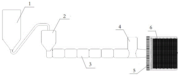
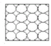
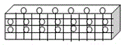
[0031] Such as figure 1 As mentioned above, PS (polystyrene) particles are put into the feeder, dried at 50-65°C for 3 hours, and then enter the vacuum section of the equipment to melt at a high temperature of 170-240°C, and the light-guiding particles (SiO 2、 TiO 2、 Al 2 o 3、 ZnO, MgO, ZrO 2 or organic silicon) are simultaneously dried at 60-80°C, melted at a high temperature of 180-255°C, and then added 2.185%-4.5% of light-guiding particles (SiO2) per ton of raw material particles through a precision distribution system 2、 TiO 2、 Al 2 o 3、 ZnO, MgO, ZrO 2 Or organic silicon) ratio melting through the light guide particle distribution die, evenly distributed in the melting plate, such as figure 2 and image 3 shown.

[0032] This product is made of light-guiding particles (SiO 2、 TiO 2、 Al 2 o 3、 ZnO, MgO, ZrO 2 or organic si...


PUM


Abstract

The invention discloses a printing-free light guide plate production method and a printing-free light guide plate. The production method comprises the following steps: polystyrene particles are fused at a high temperature to form a fusant, light guide particles are added in the polystyrene fusant, and then the mixed fusant is extruded and discharged through a light guide particle distribution die orifice, so that the light guide particles are arranged according to the extrusion discharge direction. According to the invention, through the light guide function of the light guide particles and a knurling structure, the printing-free light guide plate is a novel optical material which can effectively and uniformly transform the point light source of an LED lamp bead into an area source under the irradiation of a side light source of the LED lamp bead, wherein the light guide particles accounts for a certain proportion of a polystyrene sheet material and are uniformly distributed in the polystyrene sheet material.

Description

technical field [0001] The invention relates to a light guide plate and a production method thereof. Background technique [0002] Light gnide plate (hereinafter referred to as LGP) is one of the indispensable optical materials in LED panel light components and backlight modules. The production process is as follows: [0003] 1. Plate extrusion molding (PMMA particles are heated and dried → high temperature vacuum melting → die extrusion molding); [0004] 2. Cutting and polishing (formed plate → cutting small plate → edge polishing); [0005] 3. Dot screen printing (plate cleaning→ink mixing→dot printing→drying treatment) or laser dot printing (plate cleaning→laser dot equipment dotting→clean the board surface); [0006] 4. Reflective film coating; [0007] The main production process of light guide plate (LGP) is dot printing, which needs to go through the following steps: [0008] (Tear off the protective film → dot printing light guide ink → IR drying) and ot...

Claims


Application Information

Patent Timeline
Patent Type & Authority Applications(China)
IPC IPC(8): B29D11/00G02B6/00
Inventor 程媛媛
Owner CHONGQING LINGCHUANGFU PHOTOELECTRIC TECH
Why Eureka
Try Eureka