Moment balance drilling machine

A torque balance and drilling machine technology, which is applied in drilling equipment, earthwork drilling, driving devices for drilling in wellbore, etc.

Active Publication Date: 2015-05-13
TAIZHOU SANFU SHIP ENG CO LTD
View PDF5 Cites 4 Cited by
  • Summary
  • Abstract
  • Description
  • Claims
  • Application Information

AI Technical Summary

Problems solved by technology

[0002] At present, the drilling machines used in drilling engineering are all driven by the drill rod to rotate the drill bit to drill holes. When the drill rod rotates, a large rotational moment will be generated, and the drill rod will usually be twisted or bent.

Method used


Image

  • Moment balance drilling machine
  • Moment balance drilling machine
  • Moment balance drilling machine

Examples


Embodiment Construction

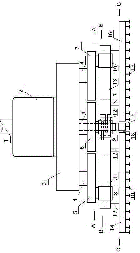
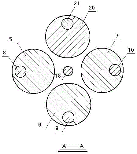
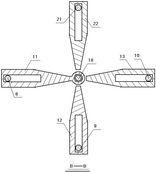
[0015] Accompanying drawing is a kind of concrete embodiment of the present invention, and this embodiment drilling rod 1 lower end is provided with motor 2, and motor lower end is provided with transfer case 3, and transfer case bottom outputs four five-point shafts 4, four five-point shafts A disk 5, two disks 6, three disks 7, and four disks 20 are respectively fixed at the lower end of the lower end, and a sub-axis 8 is fixed at a certain length from the center of the circle on the first disk, and a sub-axis is arranged on a rectangular hole in a rectangular arm 11. Among them, a rectangular arm is hinged to the sextant shaft by one end of the sextant shaft 18, the upper end of the sextant shaft is fixed in the middle of the lower part of the transfer case, and the lower part of a rectangular arm is fixed to a drill arm 14 through two connecting shafts 17; The two discs are fixed with a dichotomous shaft 9 at a certain length from the center of the circle, and the dichotomo...


PUM


Abstract

Provided is a moment balance drilling machine. A first split shaft is arranged in a rectangular hole of a first rectangular arm. One end, close to a sixth split shaft, of the first rectangular arm is hinged to the sixth split shaft. The upper end of the sixth split shaft is fixed on the middle of the lower portion of a transfer case. The lower portion of the first rectangular arm is fixed on a first drilling arm through two connecting shafts. A second split shaft is arranged in a rectangular hole of a second rectangular arm. One end, close to the sixth split shaft, of the second rectangular arm is hinged to the sixth split shaft. The lower portion of the second rectangular arm is fixed on a second drilling arm through two connecting shafts. A third split shaft is arranged in a rectangular hole of a third rectangular arm. One end, close to the sixth split shaft, of the third rectangular arm is hinged to the sixth split shaft. The lower portion of the third rectangular arm is connected with a third drilling arm through two connecting shafts. A fourth split shaft is arranged on a rectangular hole of a fourth rectangular arm. One end, close to the sixth split shaft, of the fourth rectangular arm is hinged to the sixth split shaft. The lower portion of the fourth rectangular arm is fixed on a fourth drilling arm through two connecting shafts.

Description

technical field [0001] The invention relates to a drilling machine, in particular to a torque balance drilling machine used in drilling engineering. Background technique [0002] At present, the drilling machines used in the drilling engineering are all driven by the drill rod to rotate the drill bit to drill holes. When the drill rod rotates, a large rotational moment will be generated, and the drill rod will usually be twisted or bent. Contents of the invention [0003] The present invention overcomes the above disadvantages and provides a torque balance drilling machine. [0004] The present invention is achieved through the following technical solutions: [0005] A torque balance drilling machine, the lower end of the drill rod is provided with a motor, the lower end of the motor is provided with a transfer case, the lower part of the transfer case outputs four five-point shafts, and the lower ends of the four five-point shafts are respectively fixed with a disc and t...

Claims


Application Information

Patent Timeline
Patent Type & Authority Applications(China)
IPC IPC(8): E21B4/16E21B4/04
CPCE21B4/04E21B4/16
Inventor 刘玉秋
Owner TAIZHOU SANFU SHIP ENG CO LTD
Why Eureka
Try Eureka