
Gas turbine transition section structure

A gas turbine and transition section technology, applied in the combustion chamber, combustion method, combustion equipment and other directions, can solve the problems of easy deformation of the side wall of the transition section, and achieve the effect of reducing complexity, facilitating disassembly and assembly, and preventing the opening from becoming smaller.

Active Publication Date: 2015-05-13
CHINA UNITED GAS TURBINE TECH CO LTD
View PDF9 Cites 1 Cited by
  • Summary
  • Abstract
  • Description
  • Claims
  • Application Information

AI Technical Summary

Problems solved by technology

[0006] The technical problem to be solved by the present invention is to improve the structure of the transition section of the gas turbine in the prior art, and solve the situation that the side wall of the transition section is easily deformed

Method used


Image

  • Gas turbine transition section structure
  • Gas turbine transition section structure
  • Gas turbine transition section structure

Examples


Embodiment Construction

[0028] Embodiments of the present invention will be further described in detail below in conjunction with the accompanying drawings and examples. The following examples are used to illustrate the present invention, but should not be used to limit the scope of the present invention.

[0029] In the description of the present invention, it should be noted that the terms "center", "longitudinal", "transverse", "upper", "lower", "front", "rear", "left", "right", " The orientations or positional relationships indicated by "vertical", "horizontal", "top", "bottom", "inner" and "outer" are based on the orientations or positional relationships shown in the drawings, and are only for the convenience of describing the present invention and Simplified descriptions, rather than indicating or implying that the device or element referred to must have a particular orientation, be constructed and operate in a particular orientation, and thus should not be construed as limiting the invention. ...


PUM


Abstract

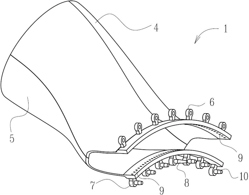
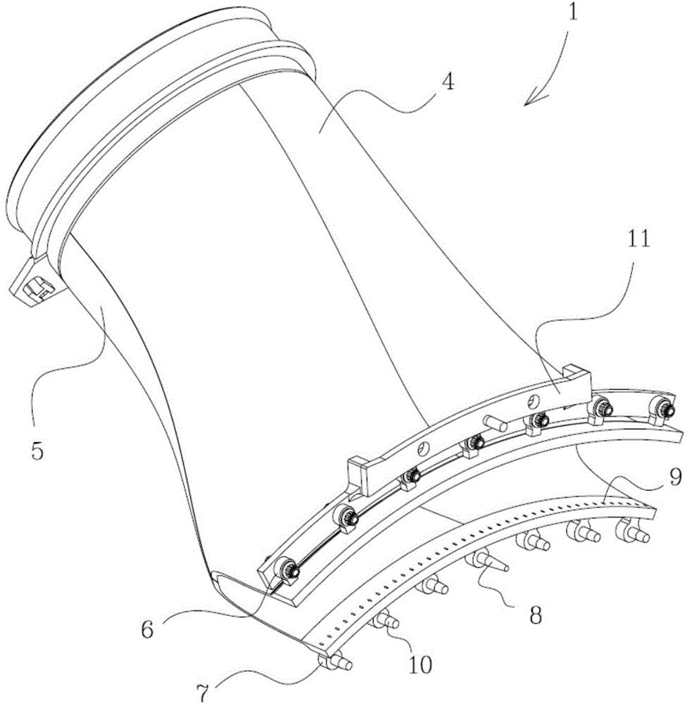
The invention relates to the technical field of gas turbines and provides a gas turbine transition section structure. The gas turbine transition section structure comprises an upper wall and a lower wall, the outlet end of the upper wall is separated from the outlet end of the lower wall and the upper wall and the lower wall are each of a fan shape. Side sealing elements are arranged at the outer sides of the upper wall and the lower wall and enable sealing to be achieved between the two sides of the upper wall and the lower wall; first connecting pieces are fixed on the upper wall and used for fixedly connecting the upper wall and a turbine inner casing; limiting pieces are fixed on the lower wall and used for limiting the radial movement of the lower wall; the side sealing elements comprise second connecting pieces used for connecting with the turbine inner casing. The gas turbine transition section structure can effectively prevent an opening of an outlet end of a transition section from getting smaller as a result of a ratchet effect, and complexity of the structure is reduced, so that the disassembly is facilitated. In addition, as an original side wall structure prone to be deformed due to heat stress does not exist any longer, side wall warping and even fracture at the outlet end of the transition section structure caused by low-cycle fatigue as well as dropping of a sealing structure are avoided; air is prevented from entering a thermal channel directly.

Description

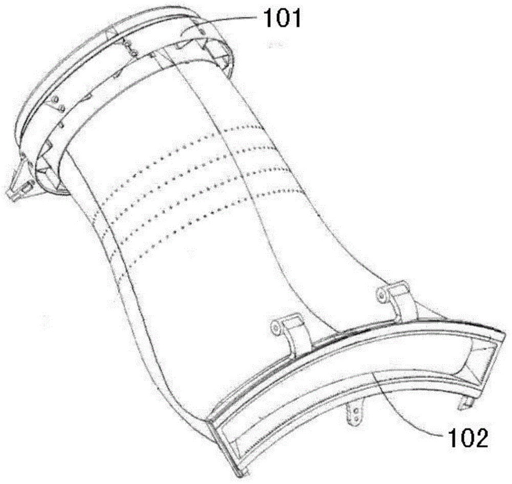
technical field [0001] The invention relates to the technical field of gas turbines, in particular to a transition section structure of a gas turbine. Background technique [0002] A conventional gas turbine transition section includes a circular inlet 101 and a fan-shaped outlet 102, see figure 1 . Due to the special structure of the fan-shaped outlet 102 in the transition section, deformation caused by low-cycle fatigue is prone to occur during long-term work. When the operation of starting and stopping the gas turbine is repeated, the thermal stress of the fan outlet 102 of the transition section is prone to cause low cycle fatigue. At this time, at the fan-shaped outlet 102 of the transition section, since the thickness of the side wall is smaller than that of the upper and lower walls, the upper and lower walls with higher hardness are not easily deformed due to their higher strength, while in the side wall it will Cause forced thermal deformation, the so-called "rat...

Claims


Application Information

Patent Timeline
IPC IPC(8): F23R3/60
Inventor 刘小龙吕煊查筱晨
Owner CHINA UNITED GAS TURBINE TECH CO LTD
Learn More