
A portable card reader

A card reader and portable technology, applied in the field of card readers, can solve the problems of easy breakage, occupying space, and being susceptible to external vibration interference, so as to reduce the occupied space, avoid antenna damage, and buffer external vibration. Effect

Active Publication Date: 2018-01-16
TENDYRON CORP
View PDF5 Cites 0 Cited by
  • Summary
  • Abstract
  • Description
  • Claims
  • Application Information

AI Technical Summary

Problems solved by technology

[0002] At present, the antenna used by the card reader is usually a hard antenna, and the connection structure between the antenna and the circuit is usually an integrated structure. This antenna structure takes up a certain space and is prone to breakage. It is easily disturbed by external vibrations, which will adversely affect the normal use of the card reader. With the continuous expansion of smart card application scenarios, the demand for card readers is also increasing. The hard antenna integrated with the circuit has been unable to meet the needs of people. Requirements for the portability and shock resistance of card readers

Method used


Image

  • A portable card reader
  • A portable card reader
  • A portable card reader

Examples


Embodiment

[0034] Such as Figures 1 to 5 As shown, only its structure is illustrated to illustrate its principle, and the actual structure can be designed by those of ordinary skill in the art.

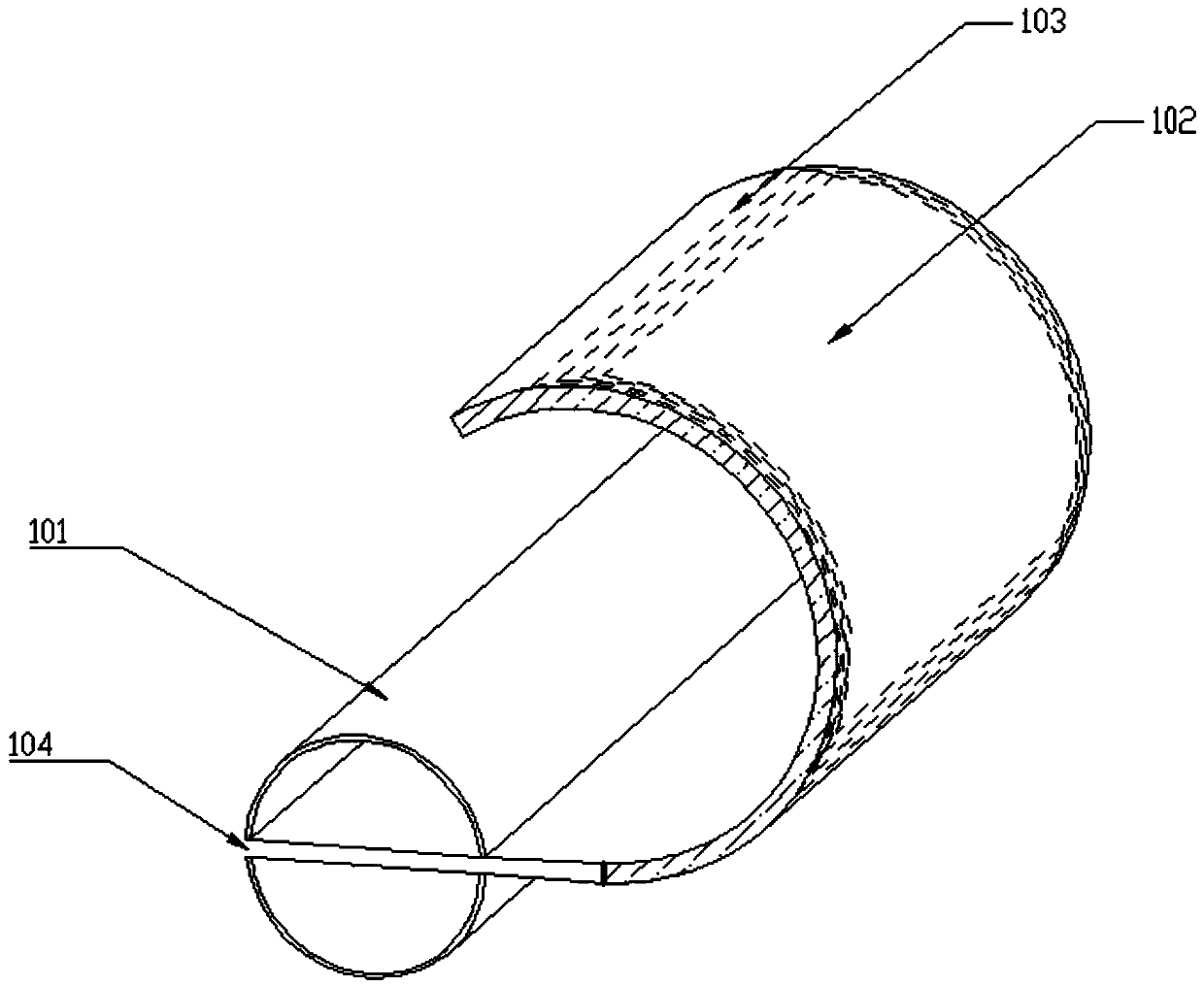
[0035] Such as Figures 1 to 5 As shown, the present invention provides a portable card reader, which is characterized in that it includes a circuit, a support shaft 101, and a flexibly deformable antenna panel 102 connected to the support shaft 101, wherein the flexibly deformable antenna panel 102 connected to the support shaft 101 The panel 102 is provided with a flexibly deformable antenna coil 103, and the flexibly deformable antenna coil 103 is electrically connected to the circuit for transmitting or receiving information. The antenna panel 102 is provided with a first slot, and the side wall of the antenna panel 102 is provided with a The opening of the first card slot, the first card slot extends to the inside of the antenna panel 102 . ;

[0036] in, figure 1 , 2 It is a schemati...

Embodiment approach

[0060] Such as Figure 4 As shown, the portable card reader is a contact card reader, and the contact card is inserted into the card reader from the card slot 104, and the card slot 104 extends to the inside of the flexible panel 102, and is positioned by the card position part in the card slot 104, so that The electronic chip on the contact card is contacted and connected with the card reader module in the card slot 104 to realize the information interaction between the card reader and the contact card;

[0061] Such as Figure 5 As shown, the portable card reader is a non-contact card reader. When the non-contact card reader is in a non-working state, the flexible antenna panel 102 can be accommodated and wound inside the support shaft 101. When the non-contact card reader When work is required, the flexible antenna panel 102 can be unfolded into a flat state, and an antenna coil is arranged inside the flexible antenna panel 102, which can exchange information with a non-co...


PUM


Abstract

The present invention provides a portable card reader, which includes a circuit, a support shaft, and a flexibly deformable antenna panel connected to the support shaft, wherein the flexibly deformable antenna panel connected to the support shaft is provided with a flexible A flexibly deformable antenna coil, the flexibly deformable antenna coil is electrically connected to the circuit for transmitting or receiving information, the antenna panel is provided with a first card slot, and the side wall of the antenna panel is provided with the The opening of the first card slot, the first card slot extends to the inside of the antenna panel. The card reader provided by the present invention adopts the design of the flexible antenna panel with a separate structure from the circuit, and the flexible antenna panel of the card reader in the non-working state can be wound on the outside of the outer wall of the card reader support shaft, which significantly improves the portability of the card reader. sex.

Description

technical field [0001] The invention relates to a card reader, in particular to a portable card reader. Background technique [0002] At present, the antenna used by the card reader is usually a hard antenna, and the connection structure between the antenna and the circuit is usually an integrated structure. This antenna structure takes up a certain space and is prone to breakage. It is easily disturbed by external vibrations, which will adversely affect the normal use of the card reader. With the continuous expansion of smart card application scenarios, the demand for card readers is also increasing. The hard antenna integrated with the circuit has been unable to meet the needs of people. Requirements for the portability and shock resistance of the card reader. Contents of the invention [0003] In order to solve at least one of the above-mentioned problems, the present invention provides a portable card reader, which is characterized in that it includes a circuit, a sup...

Claims


Application Information

Patent Timeline
Patent Type & Authority Patents(China)
IPC IPC(8): G06K7/00
Inventor 李东声
Owner TENDYRON CORP
Learn More