
Metering type lead screw color master proportional valve

A proportional valve and color masterbatch technology, applied in the field of proportional valve components, can solve the problems affecting product quality, low tightness of production lines, and integration of production lines, etc., to achieve the effect of fully automated work and reliable mixing

Inactive Publication Date: 2015-05-20
明利机电(深圳)有限公司
View PDF0 Cites 5 Cited by
  • Summary
  • Abstract
  • Description
  • Claims
  • Application Information

AI Technical Summary

Problems solved by technology

[0002] For processing lines such as injection molding that include color masterbatch, a proportional valve is set on it to mix the color masterbatch and raw materials quantitatively and then supply them to molding machines such as injection molding machines or presses for molding; quantitative mixing is generally weighing mixing; Since the color masterbatch and raw materials are mostly pellets or granular powder, once the color masterbatch and raw materials are mixed unevenly, it will affect the product quality during the molding process; in order to mix reliably, the existing proportional valve will increase the blowing or stirring mixing. structure, which can produce the effect of mixing materials, but the mixing structure is too complicated, and it is very easy to damage the raw materials; furthermore, the proportional valve of the existing production line is only used for quantitative weighing and feeding after mixing, which is different from the whole The tightness of the production line is small, the expansion performance of the whole equipment is poor, and it cannot be integrated with the production line to achieve reliable, continuous and efficient feeding

Method used


Image

  • Metering type lead screw color master proportional valve
  • Metering type lead screw color master proportional valve
  • Metering type lead screw color master proportional valve

Examples


Embodiment Construction

[0029] The present invention is described by taking a specific metering screw masterbatch proportional valve as an embodiment.

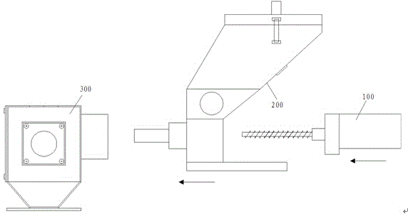
[0030] Such as figure 1 As shown, the metering screw color masterbatch proportional valve of the present invention is characterized in that: it includes a feeding assembly 100, a feeding assembly 200 and a mixing valve assembly 300, and the feeding assembly quantitatively transports the color masterbatch in the feeding assembly to In the mixing valve assembly;

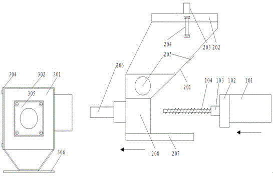
[0031] Such as figure 2 As shown, the feeding assembly includes a stepping motor 101, and the stepping motor drives a feeding screw 104 to rotate and feed;

[0032] Such as figure 2 As shown, the blanking assembly includes a color masterbatch hopper 201 for storing color masterbatch, the bottom of the color masterbatch hopper is a discharge chamber 208, and the entire color masterbatch hopper is installed on a horizontal slider base 207; the discharge chamber contains Inlet and outlet, ...


PUM


Abstract

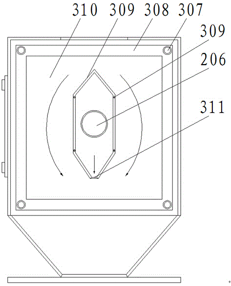
The invention discloses a metering type lead screw color master proportional valve which comprises a feeding assembly, a discharging assembly and a mixing valve assembly, wherein the feeding assembly is used for quantitatively conveying a color master in the discharging assembly into the mixing valve assembly; the feeding assembly comprises a motor, wherein the motor drives a feeding lead screw to rotatably feed; the discharging assembly comprises a color master hopper used for storing the color master, a discharging chamber is arranged at the bottom of the color master hopper, and the whole color master hopper is mounted on a horizontal sliding block base; the discharging chamber comprises an inlet and an outlet, wherein a discharging pipe is mounted at the outlet, and the end part of the feeding lead screw is arranged in the discharging pipe after the feeding lead screw extends to the outlet of the discharging chamber from the inlet of the discharging chamber; the mixing valve assembly comprises a static base, wherein the interior of the static base is hollow, a distributing cone with a cavity is arranged in the static base, and a raw material inlet is formed in a position, which corresponds to the position of the top end of the distributing cone, of the top end of a shell of the static base; and an opening communicated with the cavity of the distributing cone is formed in the bottom of the distributing cone.

Description

technical field [0001] The invention relates to a proportional valve assembly, which is specifically used for quantitatively mixing color masterbatch and raw materials. Background technique [0002] For processing lines such as injection molding that include color masterbatch, a proportional valve is set on it to mix the color masterbatch and raw materials quantitatively and then supply them to molding machines such as injection molding machines or presses for molding; quantitative mixing is generally weighing mixing; Since the color masterbatch and raw materials are mostly pellets or granular powder, once the color masterbatch and raw materials are mixed unevenly, it will affect the product quality during the molding process; in order to mix reliably, the existing proportional valve will increase the blowing or stirring mixing. structure, which can produce the effect of mixing materials, but the mixing structure is too complicated, and it is very easy to damage the raw mate...

Claims


Application Information

Patent Timeline
Patent Type & Authority Applications(China)
IPC IPC(8): B29B7/04B29B7/22B29B7/24
Inventor 雷宗贤余立伍黄全军
Owner 明利机电(深圳)有限公司
Learn More