
Oil drive variable pitch quadrotor type multifunctional fire-fighting unmanned aerial vehicle

A variable-pitch, four-rotor technology, applied in the field of drones, can solve problems such as slow and limited rescue speed, endangering the lives of firefighters, etc., and achieve good fire-fighting effects

Active Publication Date: 2015-05-20
曹兵 +1
View PDF7 Cites 31 Cited by
  • Summary
  • Abstract
  • Description
  • Claims
  • Application Information

AI Technical Summary

Problems solved by technology

[0002] At present, when a fire breaks out, fire trucks are dispatched to fight the fire, but the limitations of fire trucks are very large. For example, if a fire breaks out in a high-rise building, the height of the ladder and fire water cannon spraying water is limited, and there will be situations where it is impossible to rescue and cause major property damage. Loss and casualties, if the firefighters enter the building to rescue people or fire, it will endanger the firefighters' lives, and the speed of rescue is slow
Another example is the old urban areas of some cities, where the lanes are narrow and the traffic is congested. When a fire breaks out, fire trucks often cannot get in and cannot arrive at the fire scene in time.

Method used


Image

  • Oil drive variable pitch quadrotor type multifunctional fire-fighting unmanned aerial vehicle
  • Oil drive variable pitch quadrotor type multifunctional fire-fighting unmanned aerial vehicle
  • Oil drive variable pitch quadrotor type multifunctional fire-fighting unmanned aerial vehicle

Examples


Embodiment Construction

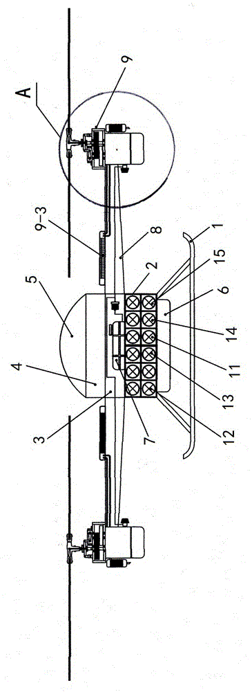
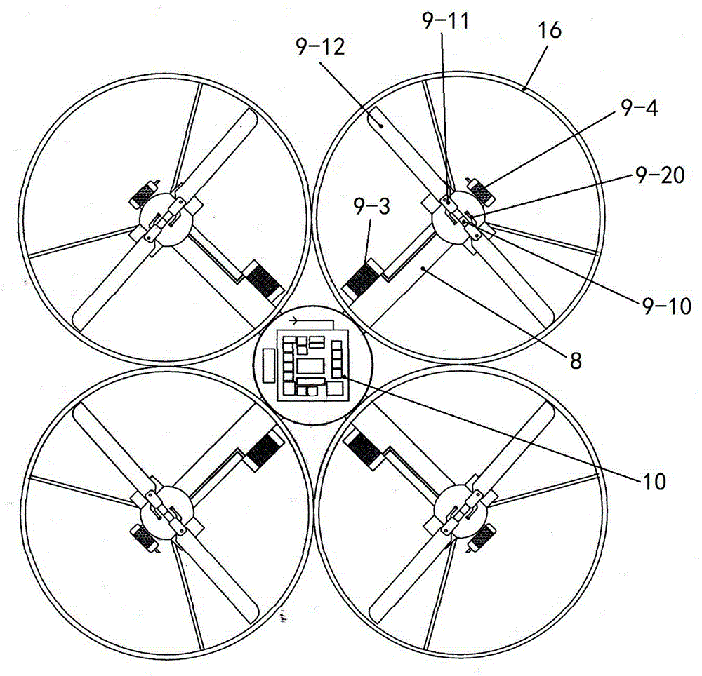
[0012] refer to figure 1 —3, it includes the cabin body and landing gear 1, the landing gear is fixed on the bottom of the cabin body, the cabin body is divided into material storage cabin 2, fuel storage cabin 3, electric control cabin 4 and umbrella cabin 5 from bottom to top, the outside of the bilge An airbag 6 is installed, and an autopilot module 10 is arranged in the electronic control cabin; a fuel tank 7 is installed in the fuel storage cabin, and four arms 8 are fixed outside the cabin, and a rotor mechanism 9 is installed on the outer end of each arm;

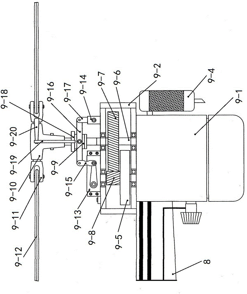
[0013] Rotor mechanism 9 comprises engine 9-1 and reduction box 9-2, and described engine is fixed on the outer end of machine arm, and reduction box is located at the top of engine, and reduction box is fixed on the machine arm, and the bottom of engine has safety air bag, The radiator 9-3 of engine is fixed on the machine arm top, and engine and radiator are connected by pipeline, and muffler 9-4 is also connected ...


PUM


Abstract

The invention discloses an oil drive variable pitch quadrotor type multifunctional fire-fighting unmanned aerial vehicle, relating to the field of unmanned aerial vehicles. The invention mainly aims at solving the problems that a conventional fire fighting truck is large in fire fighting limitations and the like. The unmanned aerial vehicle comprises a cabin, an undercarriage and an airbag, wherein a fuel tank is arranged in a fuel storage bin; engine arms are arranged outside the cabin; the outer ends of the engine arms are connected with rotor mechanisms; the airbag is arranged at the bottom of an engine of the rotor mechanisms; radiators are arranged on the tops of the engine arms; an power output shaft of each engine is connected with a centrifugal clutch in a reduction box; a driven gear on a main shaft is meshed with a driving gear on the centrifugal clutch; a variable pitch disc is arranged on the main shaft in a sleeving manner; rotor heads are fixed on the main shaft and are connected with the rotors in a clamping mode; the rotors are connected with one another in the clamping mode; a rocker arm of a servo rudder is connected with a connecting rod; the connecting rod is connected with a variable pitch disc shifting fork; a fixing seat is connected with the variable pitch disc shifting fork by virtue of a swing connecting rod; the variable pitch disc shifting fork is connected to the variable pitch disc; a screw pitch is arranged at the horizontal axis of the variable pitch disc and the rear end of a rotor clamp pull rod in the sleeving manner; and the rotor clamp pull rod is fixed on a rotor clamp. The unmanned aerial vehicle has the advantage of being not subjected to space limitation.

Description

Technical field: [0001] The invention relates to the field of unmanned aerial vehicles, in particular to a fire-fighting unmanned aerial vehicle. Background technique: [0002] At present, when a fire breaks out, fire trucks are dispatched to fight the fire, but the limitations of fire trucks are very large. For example, if a fire breaks out in a high-rise building, the height of the ladder and fire water cannon spraying water is limited, and there will be situations where it is impossible to rescue and cause major property damage. Loss and casualties, if the firefighters enter the building to rescue people or put out the fire, it will endanger the life safety of the firefighters, and the rescue speed is slow in addition. Another example is the old urban areas of some cities, where the lanes are narrow and the traffic is jammed. When a fire breaks out, fire trucks often cannot get in and cannot arrive at the fire scene in time. Invention content: [0003] The technical pr...

Claims


Application Information

Patent Timeline
IPC IPC(8): B64C39/02A62C3/00
Inventor 曹兵祁正岩
Owner 曹兵
Learn More