Rotary swatting fire extinguisher

A fire extinguisher and rotating shaft technology, applied in the field of fire extinguishers, can solve the problems of increased labor, equipment and cost, slow fire extinguishing speed, unsatisfactory effect, etc., to achieve the effect of easy carrying on the back, fast fire extinguishing speed, and reduced physical exertion

Inactive Publication Date: 2012-01-11
田昌华
View PDF6 Cites 6 Cited by
  • Summary
  • Abstract
  • Description
  • Claims
  • Application Information

AI Technical Summary

Problems solved by technology

At present, traditional forest fire-fighting equipment such as wind fire extinguishers, Fengshui fire extinguishers, etc., have slow fire extinguishing speeds and unsatisfactory effects. Fire extinguishing mops are needed as auxiliary fire extinguishing tools to clean up the fire scene, which increases the amount of labor, equipment and cost. Finally, if the fire site is not cleaned up in time, it will easily cause resurgence and bring greater losses.

Method used


Image

  • Rotary swatting fire extinguisher
  • Rotary swatting fire extinguisher
  • Rotary swatting fire extinguisher

Examples


Embodiment 1

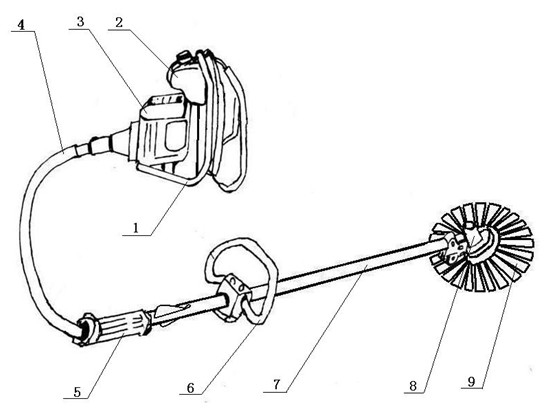
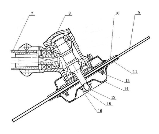
[0025] like figure 1 and figure 2 As shown, the oil pot 2 is installed on the top of the gasoline engine 3, so that gasoline can flow into the gasoline engine 3 under its own gravity, and the oil pot 2 and the gasoline engine 3 are installed on the back frame 1 as a power source, and the back frame 1 has straps for convenience. The staff carries the power source on their shoulders, the transmission shaft of the gasoline engine 3 is connected to one end of the flexible shaft 4, and the other end of the flexible shaft 4 passes through the working rod 7 with the switch 5 and is connected to the rotating shaft 12 of the working head 8 at the front end of the working rod 7 , the switch 5 on the working rod 7 can control the speed and power of the gasoline engine 3, the handle 6 is convenient for the operator to hold, the front end of the working rod 7 is the working head 8, and the upper splint 10 is fixed on the rotating shaft 12 of the working head 8. Four holes are evenly ope...

Embodiment 2

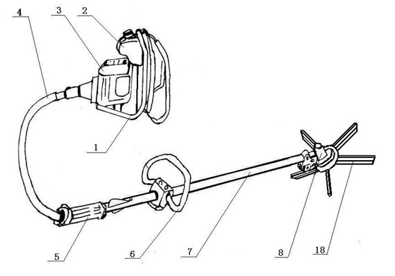
[0027] like image 3 and Figure 4 As shown, the power transmission and control part of the working head 8 of the rotary swat fire extinguisher is the same as that of Embodiment 1. The protective cover 17 is fixed on the rotating shaft 12, and the five mounting plates 22 are evenly arranged and welded on the circumference of the bottom end of the rotating shaft 12 under the protective cover 17. , the angle between every two mounting plates 22 is 72°, the mounting plates 22 are arranged parallel to the rotating shaft 12, and there are two mounting holes for installing strip type fire extinguishing soft belts 18 on the mounting plate 22, the distance between the two holes is 2cm, each Strip type fire extinguishing belt 18 is 2cm wide and 60cm long. There is also a mounting hole in the middle of the installation end of strip type fire extinguishing belt 18. Use bolt 21, nut 20 and gasket 19 to fix strip type fire extinguishing belt 18 on the mounting plate On the 22, two strip t...


PUM


Abstract

The invention discloses a rotary swatting fire extinguisher, comprising an engine (3), a flexible shaft (4), a switch (5), a working rod (7) and a working head (8), wherein the engine (3) is connected with one end of the flexible shaft (4); the other end of the flexible shaft (4) passes through the working rod (7) with the switch (5) to be connected with the spindle (12) of the working head (8) of the front end; and the spindle (12) in the working head (8) is provided with a fire extinguishing soft belt driven by the spindle (12) to rotate. According to the technical scheme disclosed by the invention, workers carry the device to simultaneously quickly extinguish fire and clear a fire scene while the fire scene of a forest fire hazard is extinguished. The rotary swatting fire extinguisher has the advantages of good effect, low cost, and good market popularization and application value, can thoroughly clean, can avoid resurgence and can be quickly reloaded. The earlier the fire hazard is extinguished to eliminate the fire hazard hidden danger, the more loss for the nation and people is saved, and less pollution is reduced for the environment.

Description

technical field [0001] The invention relates to a fire extinguisher, in particular to a rotary swat fire extinguisher. Background technique [0002] Forest fire is a natural disaster that is sudden, destructive, and difficult to deal with. Forest fire prevention is an important part of our country's disaster prevention and reduction work, an important part of the construction of the national public emergency system, an important guarantee for social stability and people's living and working in peace and contentment, and the basis and premise for accelerating forestry development and strengthening ecological construction. It is related to forestry. Resources and ecological security are related to the safety of people's lives and property, and to the overall situation of reform, development and stability. At present, traditional forest fire-fighting equipment such as wind fire extinguishers, Fengshui fire extinguishers, etc., have slow fire extinguishing speeds and unsatisfac...

Claims


Application Information

Patent Timeline
Patent Type & Authority Applications(China)
IPC IPC(8): A62C3/02A62C15/00
Inventor 田昌华
Owner 田昌华
Why Eureka
Try Eureka