Handheld hole drilling device for indoor wiring

A drilling device and indoor wiring technology, which is applied in the direction of portable mobile devices, drilling/drilling equipment, portable drilling rigs, etc., can solve the problems of high physical exertion, high production costs of devices, and the inability to guarantee the verticality of the drilling and the wall, etc. problem, to achieve the effect of reducing physical consumption, less fixed error, and simple structure

Inactive Publication Date: 2019-03-22
CHONGQING COLLEGE OF ELECTRONICS ENG
View PDF5 Cites 13 Cited by
  • Summary
  • Abstract
  • Description
  • Claims
  • Application Information

AI Technical Summary

Problems solved by technology

[0004] In the above-mentioned patents, when the device is used, there are problems that the operator consumes a lot of physical strength when working, the production cost of the device is high, and the perpendicularity between the drilled hole and the wall cannot be guaranteed.

Method used


Image

  • Handheld hole drilling device for indoor wiring
  • Handheld hole drilling device for indoor wiring
  • Handheld hole drilling device for indoor wiring

Examples


Embodiment 1

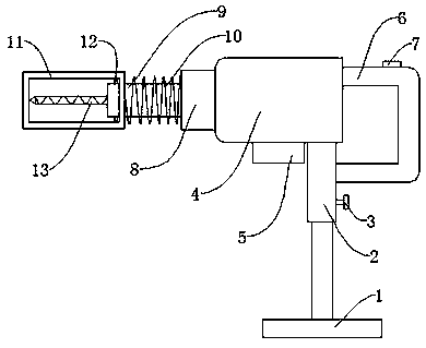
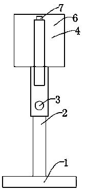
[0038] Such as Figure 1-Figure 8 As shown, a hand-held drilling device for indoor wiring of the present invention includes a base 1, a telescopic rod 2 is arranged on the upper part of the base 1, a locking switch 3 is provided on one side of the telescopic rod 2, and a housing 4 is arranged on the upper part of the telescopic rod 2. The lower part of the housing 4 is provided with a control box 5, one side of the housing 4 is provided with a handle 6, the upper part of the handle 6 is provided with a control button 7, the other side of the handle 6 is provided with a second sleeve 8, and one part of the second sleeve 8 The first sleeve 9 is provided on the side, and the outside of the first sleeve 9 is provided with an adjustment spring 10. One side of the first sleeve 9 is provided with a fixed frame 11, and one side of the fixed frame 11 is provided with a retaining ring 12. The retaining ring One side of 12 is provided with replaceable drill bit 13 , the inside of housing...

Embodiment 2

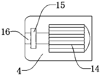
[0040] The difference between this embodiment and Embodiment 1 is that in this embodiment, the telescopic rod 2 is connected to the housing 4 by bolts, and the base 1 and the telescopic rod 2 are connected by screws, so that the height of the device can be adjusted through the telescopic rod 2 , reducing the physical consumption of the operator when working. Further, the internal stator 18 is embedded in the casing 4, the winding groove 20 is formed on the internal rotor 19, and the output shaft 16 is connected to the winding groove 20 through a spline, which can make the device more stable.

[0041] The specific working principle of the present invention is: when in use, first place the device at a suitable position through the telescopic rod 2, and fix the device through the lock switch 3, start the device by operating the button 7 to start working, and place the fixing frame 11 Compress the adjusting spring 10 on the wall of the drilled hole, align the replaceable drill bit...


PUM


Abstract

The invention discloses a handheld hole drilling device for indoor wiring. A base is included, and a telescopic rod is arranged on the upper portion of the base; a locking switch is arranged on one side of the telescopic rod; a shell is arranged on the upper portion of the telescopic rod, and a control box is arranged on the lower portion of the shell; a handle is arranged on one side of the shell, and a manipulating button is arranged on the upper portion of the handle; a second sleeve is arranged on the other side of the handle, and one side of the second sleeve is provided with a first sleeve; an adjusting spring is arranged outside the first sleeve, and a fixed frame is arranged on one side of the first sleeve; and a blocking ring is arranged on one side of the fixed frame. The handheld hole drilling device for indoor wiring has the beneficial effects that due to the fact that firstly, the telescopic rod is arranged at the bottom of the shell for height adjustment, and consumptionof the physical power of an operator in work is reduced; and secondly, through the fixed frame arranged on the front portion of the device, the structure is simple, the production cost of the device is lowered, and meanwhile the perpendicularity between hole drilling and a wall space is also guaranteed.

Description

technical field [0001] The invention relates to the technical field of drilling equipment, in particular to a hand-held drilling device for indoor wiring. Background technique [0002] Indoor wiring refers to a small integrated wiring system. When installing indoors, it is often necessary to drill holes before wiring indoors. However, the drilling equipment currently on the market consumes too much physical strength of the operators when they are in use. , the cost of production is also relatively high, and the height between the drilling and the wall cannot be guaranteed. [0003] The Chinese patent application number is: 201721192134.3, which discloses a manual mechanical drilling device, including a main support rod, a pair of spring fixing seats, a rotating compression spring, a first rotating sleeve, a handheld fixing seat, an upper fixing ring, The second rotating sleeve, the drilling head, the drilling rod, a pair of lower fixing rings, the through hole of the end an...

Claims


Application Information

Patent Timeline
Patent Type & Authority Applications(China)
IPC IPC(8): B23B45/02B23B45/14B25F5/00B25F5/02
CPCB23B45/001B23B45/003B23B45/02B25H1/0021
Inventor 李进
Owner CHONGQING COLLEGE OF ELECTRONICS ENG
Why Eureka
Try Eureka