Controllably and orderly inflated self-supporting type solar sail structure

An inflatable deployment and self-supporting technology, which is applied in the aerospace field, can solve the problems of inability to deploy the solar sail surface and poor stability, and achieve the effects of uniform tension distribution, improved stability, and improved straightness

Active Publication Date: 2015-05-20
HARBIN INST OF TECH
View PDF5 Cites 18 Cited by
  • Summary
  • Abstract
  • Description
  • Claims
  • Application Information

AI Technical Summary

Benefits of technology

This invention relates to a boat with flexible arms used for propelling or navigating through waterways. These boats have curved surfaces made up from multiple bows arranged like triangle patterns instead of traditional shapes such as circles or ellipses. When folded flat they provide more stable stability compared to regular sails due to their shape being designed specifically for navigation purposes rather than just keeping them upright during use. Additionally, these wings help distribute pressure better while still maintaining good aerodynamic performance over longer periods of time without losing its effectiveness. Overall, there's no compromise between flexibility and durability against environmental factors (such as wind).

Problems solved by technology

This patented technical solution describes how an aerial vehicle called Solar Sail (SS) uses energy stored during certain stages or phases of operation to generate thrust instead of relying solely upon fuel combustion. However, current methods have limitations such as low efficiency at launching into space because they require too much time before reaching their destination. Additionally, it may also lose effectiveness if deployed incorrectly over longer periods of time.

Method used


Image

  • Controllably and orderly inflated self-supporting type solar sail structure
  • Controllably and orderly inflated self-supporting type solar sail structure
  • Controllably and orderly inflated self-supporting type solar sail structure

Examples


Embodiment Construction

[0031] The following will clearly and completely describe the technical solutions in the embodiments of the present invention with reference to the accompanying drawings in the embodiments of the present invention. Obviously, the described embodiments are only some, not all, embodiments of the present invention. Based on the embodiments of the present invention, all other embodiments obtained by persons of ordinary skill in the art without creative efforts fall within the protection scope of the present invention.

[0032] It should be noted that, in the case of no conflict, the embodiments of the present invention and the features in the embodiments can be combined with each other.

[0033] The present invention will be further described below in conjunction with the accompanying drawings and specific embodiments, but not as a limitation of the present invention.

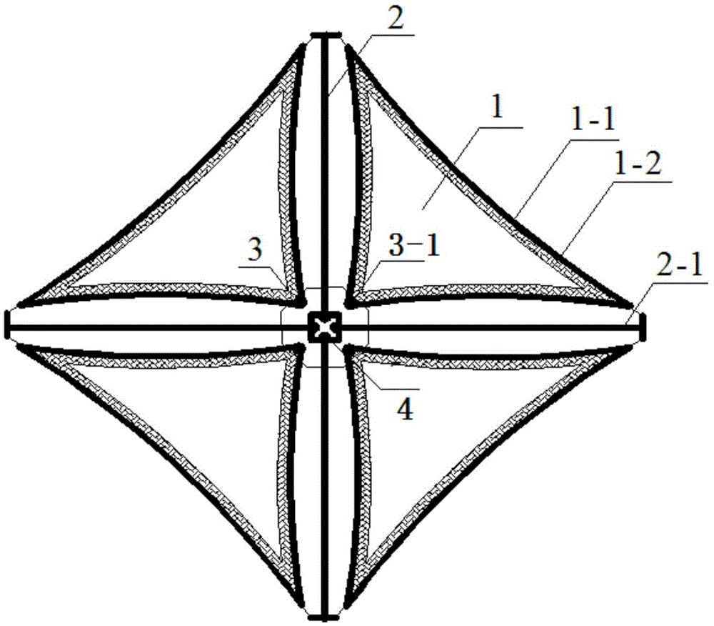
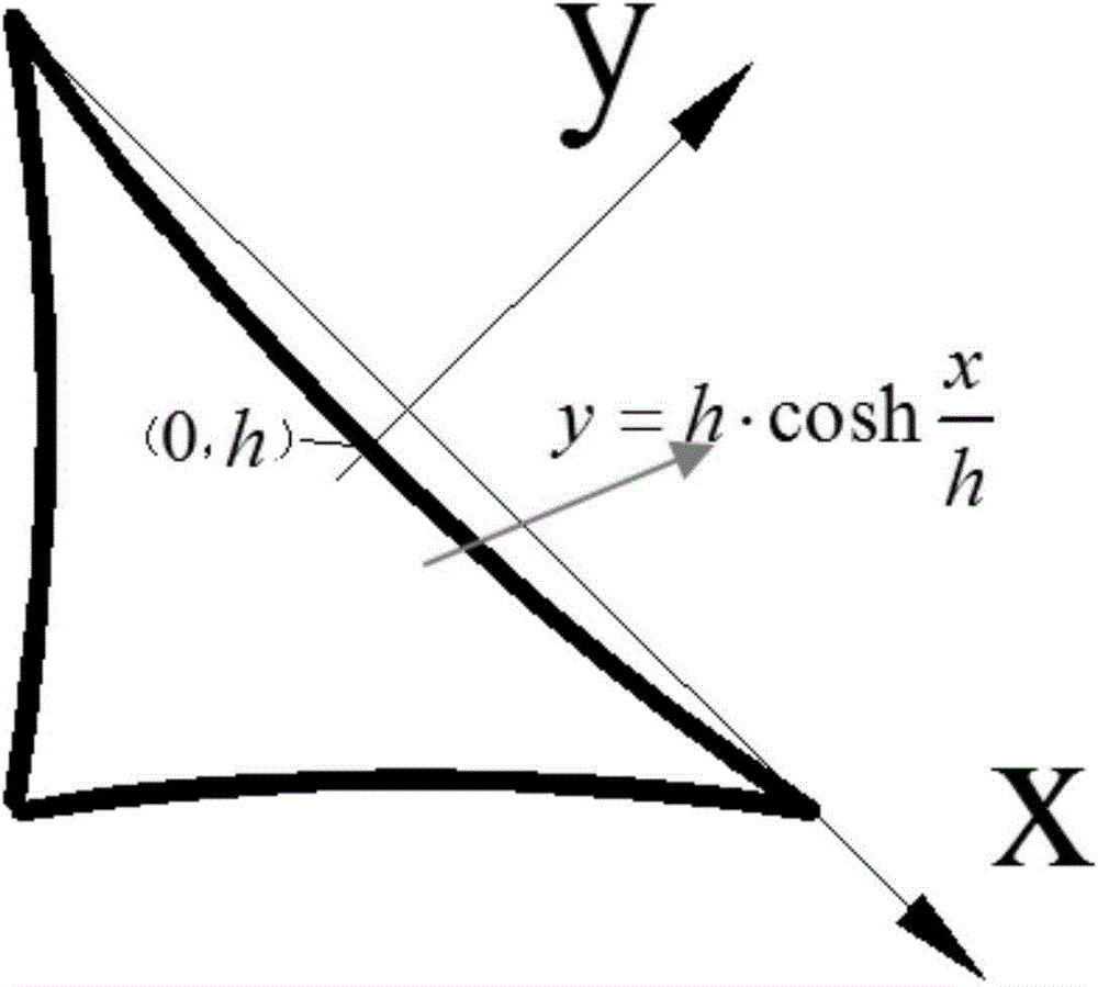
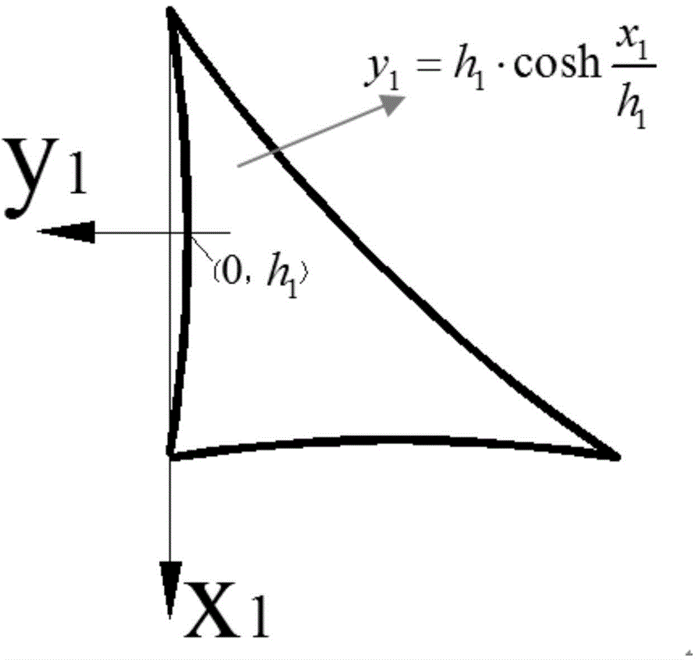
[0034] Such as Figure 1 to Figure 9 As shown, a controllable and orderly inflation self-supporting solar sail ...


PUM


Abstract

The invention relates to the field of spaceflight and discloses a controllably and orderly inflated self-supporting type solar sail structure. A sail surface approximately triangle-shaped and formed by three curves is adopted, the sail surface can be unfolded in orbit stably and orderly, and distribution gradient of internal plane stress forced on the sail surface after unfolding is reduced by 20%; a support ring with the inner diameter equal to a winding shaft is arranged at the position of rectangular vertice of the sail surface, and concentrated stress of the sail surface can be lowered; a circular opening enclosed by 4n (n is larger than or equal to 3, and n is an integer) sawteeth, and no relative movement between the vertice of the sail surface and the winding shaft can be guaranteed; four sets of inflated extension arms used for supporting the sail surface are unfolded, each set is formed by two extension arms, straightness of the inflated extension arms and rigidity of the inflated extension arms after being unfolded can be improved, the rigidity of the structure is two times of that of a structure with a single extension arm, and unfolding stability of the extension arms is improved.

Description


Claims


Application Information

Patent Timeline
Owner HARBIN INST OF TECH
Why Eureka
Try Eureka