A torsion cross beam, in particular for a composite steering axle and a motor vehicle comprising the torsion cross beam

A technology for torsion beams and beams, applied in the direction of vehicle springs, vehicle components, axles, etc., can solve problems such as unfavorable tension peaks and complicated manufacturing of torsion beams.

Inactive Publication Date: 2017-01-11
FORD GLOBAL TECH LLC
View PDF12 Cites 0 Cited by
  • Summary
  • Abstract
  • Description
  • Claims
  • Application Information

AI Technical Summary

Problems solved by technology

Such torsion beams are complex to manufacture and may have partially unfavorable tension peaks when loaded according to regulations

Method used


Image

  • A torsion cross beam, in particular for a composite steering axle and a motor vehicle comprising the torsion cross beam
  • A torsion cross beam, in particular for a composite steering axle and a motor vehicle comprising the torsion cross beam
  • A torsion cross beam, in particular for a composite steering axle and a motor vehicle comprising the torsion cross beam

Examples


Embodiment Construction

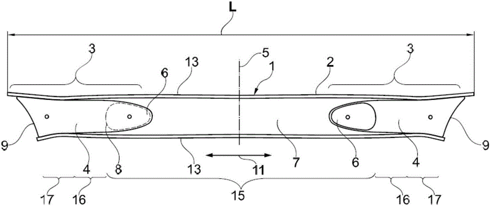
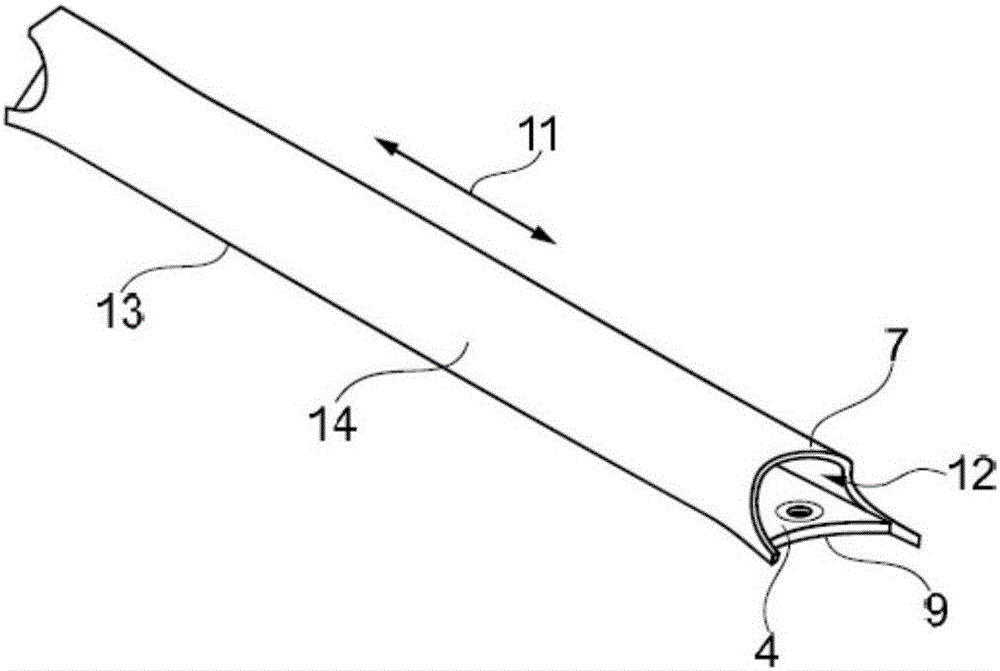
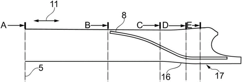
[0030] Figure 9 The unfavorable tension distribution of the torsion beam according to the prior art is shown. Such a twist beam according to the prior art with regard to its construction type is a twist beam in which an insert element is inserted into the end region of an open twist beam profile. The abutment area 100 is shown schematically. In the abutment area 100 the end of the insert element pointing towards the longitudinal center of the twist beam rests against the inside of the twist beam profile. In the abutment area, the insert element and the torsion beam profile are formed in a planar manner. In the case of prescribed loading, an unfavorable tension peak 101 occurs adjacent to the abutment region 100 .

[0031] in this case, Figure 9 A printout is shown of the tension distribution that has been built by the tension build operation using the finite element method. Such unfavorable tension peaks are intended to be prevented, which are caused by the use of the t...


PUM


Abstract

A torsion cross beam having a torsion cross beam profile in which the insert element is inserted into an end region of the torsion beam profile to form a closed cross-sectional space, wherein the insertion element is directed at the end of the longitudinal center of the torsion cross beam to form an abutment region of the torsion cross beam profile so as to fit the profile base of the torsion cross beam profile in the direction towards the end; at least in the abutment area of the torsion cross beam profile against the base of the profile, the profile base has a first cross-sectional space; the cross-section of the first cross-sectional space is curved and has a curvature greater than zero; the profile base has a curved cross-sectional space in the abutment region, and the torsion cross beam together with the insertion element form a substantially quadrilateral second cross-sectional space in the end region; and when viewed in the longitudinal direction, the torsion cross beam profile has a transition zone between the abutment region and the free end of the torsion cross beam.

Description

technical field [0001] The invention relates to a single-wall torsion beam for a torsion beam axle according to the preamble of claim 1 . Background technique [0002] EP 2 098 391 B1 discloses a torsion beam axle and a method for manufacturing a torsion beam axle in which the torsion beam of the generic type has a cross-section that varies over its length and an omega-shaped center and end part, the cross-section of the Ω-shaped center part is open and has an undercut, the cross-section of the end part is U-shaped and the end part is on the longitudinal tie rod side. Closing plates are inserted into the ends to form closed cross-sections in each section. This end serves as the connection interface with respect to the longitudinal tie rods of the torsion beam axle. Such torsion beams are complex to manufacture and can have partially unfavorable tension peaks when loaded according to regulations. [0003] US 2013 / 0264789 A1, US 8,308,175 B2, US 6,616,157 B2, US 2011 / 011518...

Claims


Application Information

Patent Timeline
Patent Type & Authority Applications(China)
IPC IPC(8): B60G21/05
CPCB60G21/051B60G2202/136B60G2206/20B60G2206/8103B60G21/0551B60B35/04B60G2202/23B60G2206/13B60G2206/722B60G2206/8201B60B35/08B60B2310/211B60B2360/141B60B2900/311B60B2900/321
Inventor 费德里科·韦尔梅尔斯基辛简斯·格洛勒拉尔夫·安德里亚斯·舍尔哈斯洛兰·考洛陶伊安德里亚斯·欣茨
Owner FORD GLOBAL TECH LLC
Why Eureka
Try Eureka