Support movement centring device

A technology of centering device and frame shifting, which is applied in mine roof support, mining equipment, earth square drilling and mining, etc., and can solve problems such as many fault points

Inactive Publication Date: 2015-05-20
李泽宇
View PDF8 Cites 3 Cited by
  • Summary
  • Abstract
  • Description
  • Claims
  • Application Information

AI Technical Summary

Problems solved by technology

In addition, some unmanned working faces have appeared in recent years, using many sensors and comp

Method used


Image

  • Support movement centring device
  • Support movement centring device
  • Support movement centring device

Examples


Embodiment approach

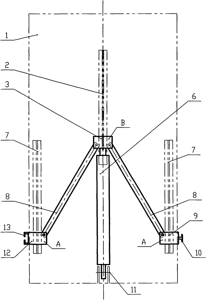
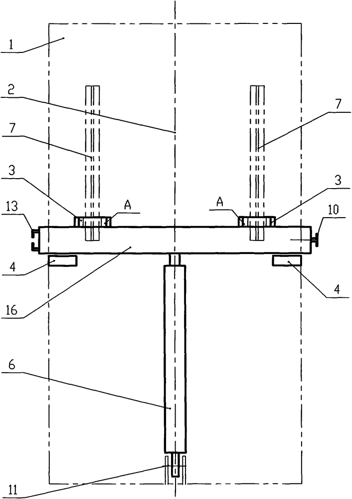
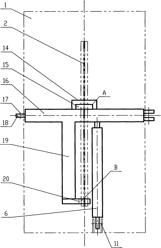
[0023] figure 1 The first embodiment of a shifting and centering device shown includes a top beam 1, a middle guide rail 2 arranged on the top beam 1, two left and right guide rails 7, a left slider 12, a right slider 9, and a middle slider Block 3, connecting rod 8 and frame moving cylinder 6. One end of the two connecting rods 8 is hinged with the middle slider 3, the other end is hinged with the left slider 12 and the right slider 9 respectively, one end of the moving cylinder 6 is hinged with the middle slider 3, and the other end is connected with the top beam through the hinge 11. 1 Hinged, the outside of the left slider 12 is provided with a vertical guide rail 13, which forms a vertical guide rail slider mechanism with the slider on the outside of the right slider 9 of the adjacent frame, consisting of the left guide rail 7, the right guide rail 7, the left slider 12 and the right slider Block 9 forms a centering mechanism. The three sliders are arranged in a triangl...


PUM


Abstract

Disclosed is a support movement centring device which is used for automatically keeping supports at the position of a designed center line when hydraulic supports of a coalface move. The support movement centring device comprises a support movement cylinder, sliding blocks, guide rails and centring mechanisms, wherein the guide rails are arranged on top beams, the sliding blocks can slide on the guide rails back and forth, and the sliding blocks are connected together through the centring mechanisms. The support movement centring device is characterized in that not more than one portion of the left side and not more than one portion of the right side of the centring mechanism of each support are in rigid connection with the centring mechanism of the adjacent support, and the rigid connection means that compression connection except gaps does not exist in a projection shadow of each centring mechanism on the horizontal plane; the support movement centring device further comprises a paralleling mechanism which enables the top beams of the supports to be kept parallel, wherein by means of the paralleling mechanism, the centring mechanisms of the supports are transversely arranged on one straight line, the straight line serves as the standard, so that the situation that the top beams are parallel to each other when the top beams are kept perpendicular to or parallel to the standard is ensured. After the structure is adopted, the centring mechanisms can automatically ensure that the distance between the center lines of the supports is equal to the designed support center distance in the process of support movement, the paralleling mechanism can automatically ensure that the direction of the supports is parallel to the advancing direction in the process of support movement, and therefore the support adjustment time can be saved, the yield is increased, and the number of control sections is reduced for automation of the whole coalface.

Description

technical field [0001] The invention relates to a device for automatically maintaining a hydraulic support at a designed center line position and keeping each support parallel to a propulsion direction during the frame moving process for a hydraulic support used for supporting a roof in an underground coal mining working face of a coal mine. Background technique [0002] Hydraulic supports are divided into two categories: fully mechanized mining hydraulic supports and sliding supports. The fully mechanized mining support is a rigid structure that can be raised and lowered consisting of a top beam, a bottom beam, a four-bar mechanism or a single pendulum. The front end of the push-pull rod at the center line of the bottom beam is hinged to the scraper conveyor and driven by a moving cylinder. The push-pull rod telescopically shifts the frame, which can ensure that the front end of the push-pull rod is at the center line of the design, but when the working surface has a large ...

Claims


Application Information

Patent Timeline
IPC IPC(8): E21D23/08E21D23/06
CPCE21D23/081E21D23/06
Inventor 李泽宇
Owner 李泽宇
Why Eureka
Try Eureka