Chamber structure for separating liquid and air, auxiliary water tank and engine cooling system

A technology of liquid-gas separation and auxiliary water tank, which is applied in the direction of engine cooling, engine components, machine/engine, etc. It can solve the problems that the air bubbles are not easy to separate and cannot fully meet the requirements of engine degassing.

Active Publication Date: 2015-05-20
BEIQI FOTON MOTOR CO LTD
View PDF7 Cites 20 Cited by
  • Summary
  • Abstract
  • Description
  • Claims
  • Application Information

AI Technical Summary

Problems solved by technology

However, due to the certain viscosity of the coolant, the air bubbles are not easy to separate from the liquid, and the existing auxiliary water tank cannot fully meet the engine's requirements for degassing

Method used


Image

  • Chamber structure for separating liquid and air, auxiliary water tank and engine cooling system
  • Chamber structure for separating liquid and air, auxiliary water tank and engine cooling system

Examples


Embodiment Construction

[0039] Specific embodiments of the present invention will be described in detail below in conjunction with the accompanying drawings. It should be understood that the specific embodiments described here are only used to illustrate and explain the present invention, and are not intended to limit the present invention.

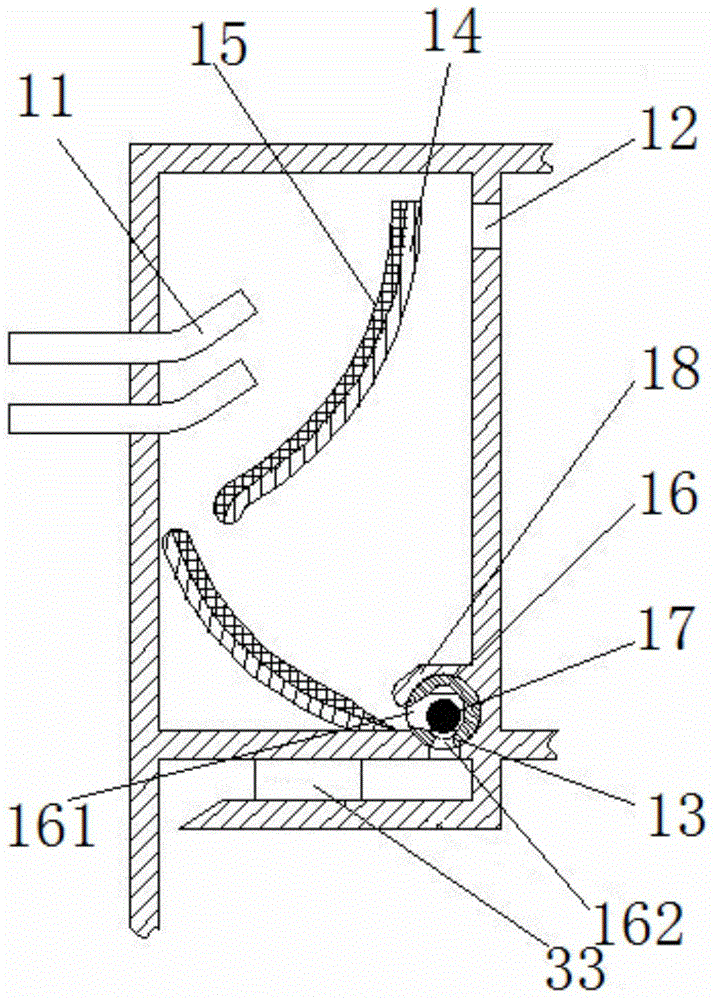
[0040] Such as figure 1 Shown is a chamber structure for liquid-gas separation according to a specific embodiment of the present invention, the chamber structure includes a liquid-gas inlet 11, an exhaust port 12 and a water outlet 13 formed on the wall of the chamber, and, the A first guide plate 14 for guiding the fluid flowing in from the liquid and gas inlet 11 to the water outlet 13 is also formed in the chamber structure. The first soft separation layer 15 of the gas mixture allows the air bubbles in the liquid-gas mixture to remain on the first soft separation layer 15 . On the one hand, the first guide plate 14 guides the flow direction of the liquid-g...


PUM


Abstract

The invention discloses a chamber structure for separating liquid and air. A first flow guide plate (14) for guiding liquid flowing into a liquid and air inlet (11) to a water outlet (13) is formed in the chamber structure, and a first soft separation layer (15) used for filtering liquid and air mixtures is arranged on the plate surface of the first flow guide plate so that bubbles in the liquid and air mixtures can be left on the first soft separation layer. On this basis, the invention discloses an auxiliary water tank including a liquid and air separation chamber (10), an air chamber (20) and a liquid chamber (30). The liquid and air separation chamber is the chamber structure. In addition, the invention discloses an engine cooling system with the chamber structure or the auxiliary water tank. The chamber structure can allow the liquid to seep out of the first soft separation layer, the bubbles are filtered out and left in the first soft separation layer, and therefore the function of separating the air and the liquid is achieved.

Description

technical field [0001] The invention relates to the field of vehicles, in particular to a chamber structure for liquid-gas separation. On this basis, the present invention also relates to an auxiliary water tank with the chamber structure. In addition, the present invention also relates to an engine cooling system comprising the auxiliary water tank. Background technique [0002] Due to the combustion of fuel (oil or gas) in the combustion chamber and the friction between mechanical parts, the engine generates a lot of heat when it is working. If the engine cannot dissipate heat in time, it will cause increased body wear, accelerated oil deterioration, and abnormal combustion. Therefore, modern engines are equipped with cooling systems to reduce heat for the body so that the engine can work at a suitable temperature, and water cooling is the main cooling method. [0003] However, due to the need to output larger power and other reasons, the coolant in the water jacket of ...

Claims


Application Information

Patent Timeline
Patent Type & Authority Applications(China)
IPC IPC(8): F01P11/02F01P11/00
Inventor 刘金波林梅友周新华刘福萍苏朝霞
Owner BEIQI FOTON MOTOR CO LTD
Why Eureka
Try Eureka