Chain sheet structure

A technology of chain pieces and joints, applied in the direction of chain links, etc., can solve the problems of stress concentration, poor effect, chain rotation obstruction, etc., to achieve the effect of dispersing stress, increasing stability and smoothness, and avoiding vibration and shaking

Active Publication Date: 2015-05-20
YABAN CHAIN INDAL
View PDF6 Cites 6 Cited by
  • Summary
  • Abstract
  • Description
  • Claims
  • Application Information

AI Technical Summary

Problems solved by technology

[0004] 1. Due to the combination of the raised waist A2 formed by punching and the linear connection surface A3, stress concentration is likely to occur at the bend between the raised waist A2 of the outer chain piece A and the connection surface A3, Therefore, the outer chain piece A will have the risk of breaking from this bend
[0005] 2. The guiding distance E1 between the waist A2 of the two outer chain pieces A is too large, so after the chain is engaged with the chainring, the allowable range of the deflection angle of the chain during transmission is too large, so that the chain will move to the left Or yaw to the right, causing vibration, noise, or chain detachment
[0006] 3. Since the connection between the waist A2 and the two joints A1 is a linear connection surface A3, the chain teeth D1 of the general chainring D are in an arc shape (such as Figure 13 As shown), therefore, matching the linear connection surface A3 of the chain will make it difficult for the sprocket D1 of the sprocket D to snap in, which will hinder the rotation of the chain, and in severe cases will cause the chain to fall off
[0007] Therefore, the structure of the outer chain piece A of the above-mentioned existing chain is not effective when the speed is changed.

Method used


Image

  • Chain sheet structure
  • Chain sheet structure
  • Chain sheet structure

Examples


Embodiment Construction

[0052] In order to further explain the technical solution of the present invention, the present invention will be described in detail below through specific examples.

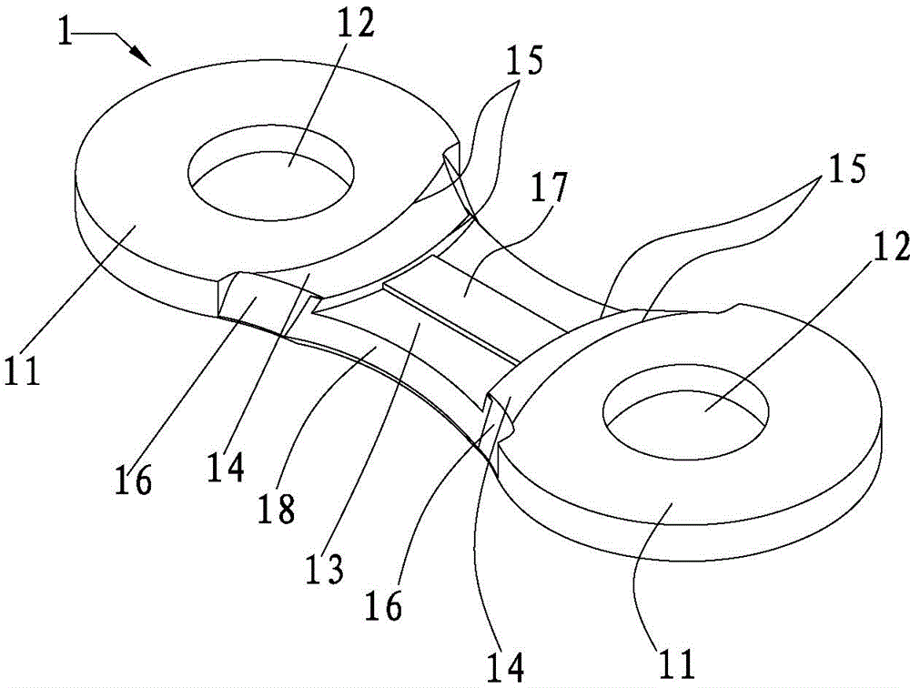
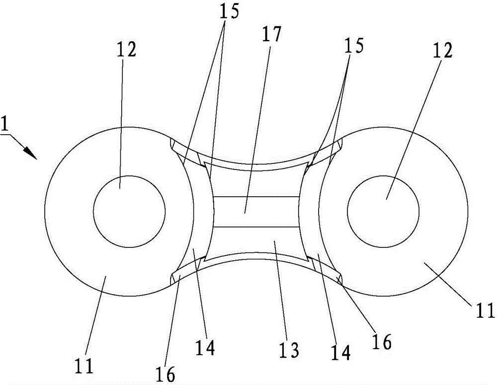
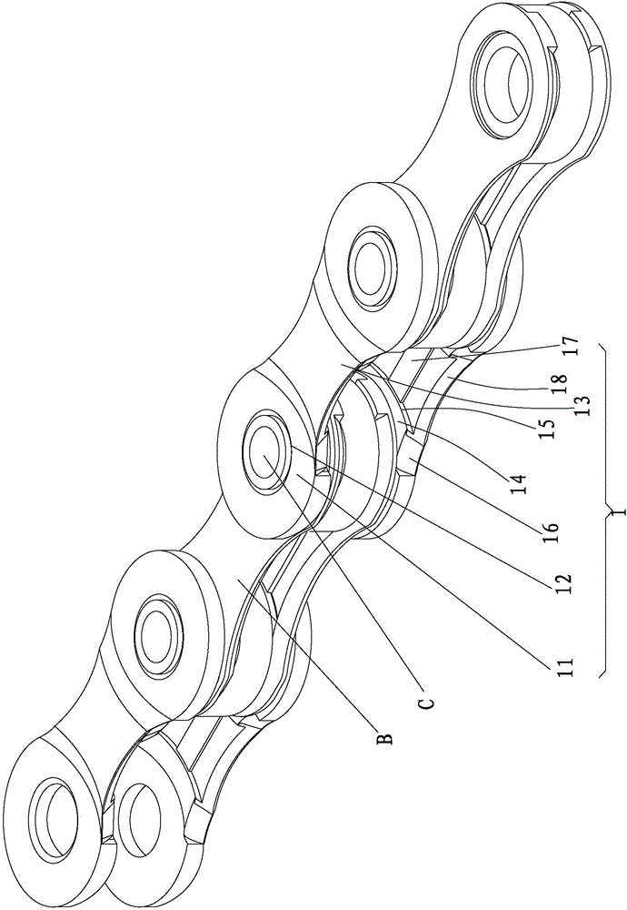
[0053] see figure 1 As shown, the embodiment of the present invention is provided with a chain piece body 1, and the two ends of the chain piece body 1 are provided with opposite arc-shaped joints 11, and the joint portion 11 is provided with a penetrating shaft hole 12, and the two On the inner side between the joints 11, there is a waist 13 that protrudes toward the outer side, is concave and thinner, and the joints between the waist 13 and the two joints 11 are respectively provided with a connecting surface 14 in the shape of a circular arc. The connection surface 14 can be an inclined surface or a plane. In this embodiment, it is described as an inclined surface. The connection surface 14 is gradually inclined from the joint portion 11 towards the waist portion 13. Using the inner and outer edges of the c...


PUM


Abstract

The invention discloses a chain sheet structure. Combining portions are arranged at the two ends of the chain sheet structure. Each combining portion is provided with an axial hole. The inner side face between the two combining portions is provided with a waist portion which relatively swells towards the outer side face and is thinned in a concaved mode. A circular arc connecting face is arranged at the connection position between the waist portion and each combining portion. The inner edge and the outer edge of each connecting face are provided with two circular arc lines, wherein the two circular arc lines are in the state that two circular arcs are arranged in a spaced mode. Each connecting face forms an outward-expanding guide-in face along the two edges of a chain sheet. One or more protruding blocks are arranged between the two connecting faces. The two sides of the waist portion are provided with opening portions which are relatively inclined. The openings are located between the two guide-in faces. By means of the two protruding blocks, meshing speed changing of chain teeth of a tooth disc can be rapidly guided, and chain transmission is stabilized.

Description

technical field [0001] The invention relates to a chain piece structure, in particular to a chain piece with a protruding block design which can contribute to fast-guided tooth plate meshing shifting and stable transmission. Background technique [0002] In order to make the chain for general bicycles fit accurately with the chainring, each chain tooth of the chainring can be cut into the space between the two outer chain pieces, so as to reduce the failure of the chain teeth due to the shaking of the chain or the vibration of the bicycle. The chances of cutting in time, so the spacing between the two outer chainrings is usually increased to accommodate the shifting of the bike at higher speeds, see Figure 11 and Figure 12 As shown, the existing chain includes two outer chain pieces A arranged oppositely in groups and two inner chain pieces B arranged oppositely in groups arranged at intervals, and are pivotally connected to each other by a chain axis C. The aforementioned...

Claims


Application Information

Patent Timeline
Patent Type & Authority Applications(China)
IPC IPC(8): F16G15/12
CPCF16G15/12
Inventor 王文滨
Owner YABAN CHAIN INDAL
Why Eureka
Try Eureka