
Distance measurement instrument

A rangefinder and housing technology, applied in the direction of measuring distance, instruments, measuring devices, etc., can solve the problems of inaccurate values, inability to adjust, and reduced accuracy of the rangefinder, so as to ensure installation accuracy, facilitate position adjustment, and improve The effect of measurement accuracy

Active Publication Date: 2015-05-20
JINHUA MAKA TECH
View PDF4 Cites 5 Cited by
  • Summary
  • Abstract
  • Description
  • Claims
  • Application Information

AI Technical Summary

Problems solved by technology

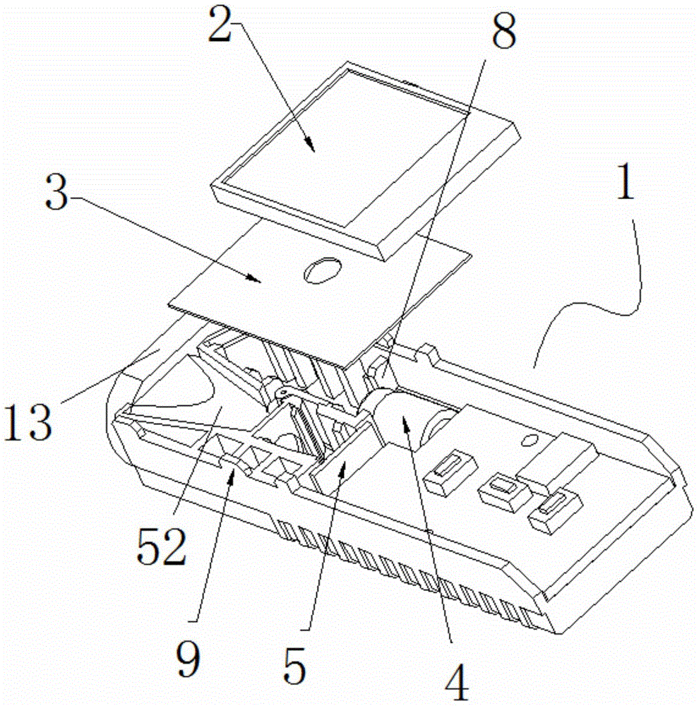
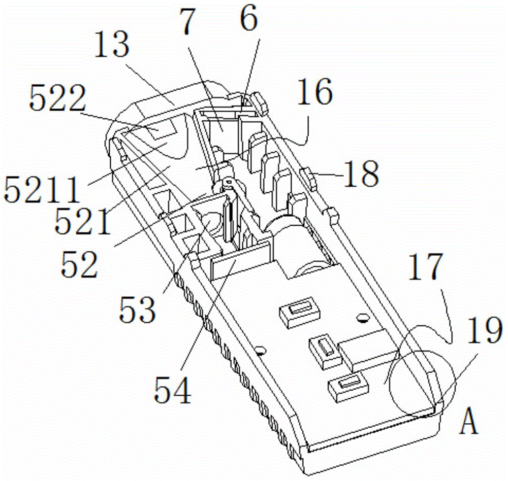
[0003] In the prior art, the hand-held range finder also has the following defects: (1) the dust-proof glass in front of the launch branch is arranged vertically to the launch channel. When the launch unit emits light towards the target direction, due to the principle of light reflection, When the light meets the glass, part of it will be reflected back, and the reflected light will be received by the receiving unit, and even the stray light coming in from the outside will be received by the receiving unit through the transmitting channel, but the light emitted to the target has not been reflected back, The existence of reflected light and stray light will inevitably affect the measurement of the target, making the measured value inaccurate and reducing the accuracy of the rangefinder; (2) When installing the components, due to the installation accuracy requirements of the transmitting unit and the receiving unit Extremely high, especially the transmitting unit. In the laser rangefinder, the transmitting unit is generally a laser component. The position of the emitted light directly affects the measurement result. Therefore, the position of the transmitting unit must be accurate, so it is necessary to adjust all directions to ensure The accuracy of the installation, but in the prior art, the installation of the transmitting unit and the receiving unit is generally to push the transmitting unit and the receiving unit into the corresponding installation cavity laterally from the rear of the housing, which is troublesome to install and push from the side into the installation cavity, only the front and rear position can be adjusted, and the up and down, left and right position adjustments are inconvenient or even impossible to adjust, so that the installation accuracy of the transmitting unit and receiving unit cannot be guaranteed; (3) the lens is an indispensable part of the rangefinder Components, the installation position of the lens is located at the front of the housing, the material of the lens is generally glass, and its installation and removal requires one hand to insert or pull out the lens directly from the installation position, which is troublesome to install and disassemble, and makes the lens in the It is easy to be damaged during installation and disassembly, so that the lens cannot be used, resulting in a waste of resources; (4) the installation of the display screen is directly installed on the housing, and there is no positioning around it. Falling, even the display data is blurred due to the shaking of the display screen, which affects the measurement of the rangefinder; (5) The installation of the main board components is also directly installed on the shell. In long-term use, the main board components are easy to loosen. Make the contact unstable, thus affecting the structure of the measurement and even the rangefinder cannot measure

Method used


Image

  • Distance measurement instrument
  • Distance measurement instrument
  • Distance measurement instrument

Examples


Embodiment Construction

[0037] In order to make the purpose, technical solutions and advantages of the embodiments of the present invention more clear, the following will clearly and completely describe the technical solutions of the embodiments of the present invention in conjunction with the drawings of the embodiments of the present invention. Apparently, the described embodiments are some, not all, embodiments of the present invention. Based on the described embodiments of the present invention, all other embodiments obtained by persons of ordinary skill in the art without creative efforts shall fall within the protection scope of the present invention.

[0038]In describing the present invention, it should be understood that the terms "center", "longitudinal", "transverse", "length", "width", "thickness", "upper", "lower", "front", " Orientation or position indicated by "back", "left", "right", "vertical", "horizontal", "top", "bottom", "inner", "outer", "clockwise", "counterclockwise", etc. Th...


PUM


Abstract

The invention discloses a distance measurement instrument. The distance measurement instrument comprises a shell, a transmitting mechanism and a receiving mechanism, which are arranged on the shell, and a light-transmitting shielding part, wherein the transmitting mechanism is provided with a transmitting channel; the light-transmitting shielding part is positioned in front of the transmitting channel and located in the shell, and has a certain inclination angle relative to the transmitting direction. The distance measurement instrument has a simple structure, and as the light-transmitting shielding part has a certain inclination angle relative to the transmitting direction, reflecting light and stray light cannot be directly reflected on a receiving assembly, and thus the measurement precision is greatly improved.

Description

technical field [0001] The invention relates to the field of measuring instruments, in particular to a hand-held distance measuring instrument. Background technique [0002] In recent years, the laser distance measurement method has been widely used in distance measurement, and the laser distance meter has also become an important tool for distance measurement. Noisy, high-sensitivity laser receivers receive the signal reflected by the target, and the distance to the target can be calculated by using the received reflected signal. The principle can be expressed by the formula: L=Td*C / 2, where , L is the distance of the target object to be measured, Td is the time delay between transmitting the pulse signal and receiving the pulse signal, C is the light propagation speed, only need to measure the delay time Td, then the distance L of the target object to be measured is enough get. Based on this principle, a laser rangefinder is manufactured, especially a hand-held laser ran...

Claims


Application Information

Patent Timeline
Patent Type & Authority Applications(China)
IPC IPC(8): G01C3/02G01S7/481G01S17/08
CPCG01C3/00G01C3/02G01S17/08G01S7/481G01S7/4814G01S7/4816
Inventor 蒋洪洲
Owner JINHUA MAKA TECH
Learn More