Public bus emergency escape rope ejection system

An escape rope, passenger car technology, applied in vehicle components, vehicle safety arrangements, pedestrian/occupant safety arrangements, etc., can solve problems such as passenger injury, easy falling, and the door cannot be opened, so as to increase the distance of linear motion and reduce jumping. fall effect

Active Publication Date: 2020-03-31
深圳市兴舞消防设备有限公司
View PDF4 Cites 0 Cited by
  • Summary
  • Abstract
  • Description
  • Claims
  • Application Information

AI Technical Summary

Problems solved by technology

[0002] With the rapid development of the economy, public transportation has become more popular, such as buses, public buses and other means of transportation have become one of the most commonly used means of transportation for people to travel. Fires caused by arson or passengers carrying inflammable and explosive materials on the bus without permission happen from time to time. When these emergencies occur, the primary task is to ensure the safe evacuation of the passengers in the bus. A fire extinguisher, but in many cases the fire extinguisher cannot completely extinguish the fire. At the same time, when a fire breaks out, the door may not be able to be opened. At this time, people can only escape by smashing the glass, but usually the windows of the bus or public bus are higher. , so people can easily fall when jumping out of the window, causing passengers to be injured

Method used


Image

  • Public bus emergency escape rope ejection system
  • Public bus emergency escape rope ejection system
  • Public bus emergency escape rope ejection system

Examples


Embodiment Construction

[0042] The present invention will be described in detail below in conjunction with the accompanying drawings and embodiments.

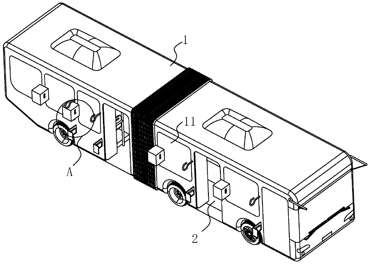
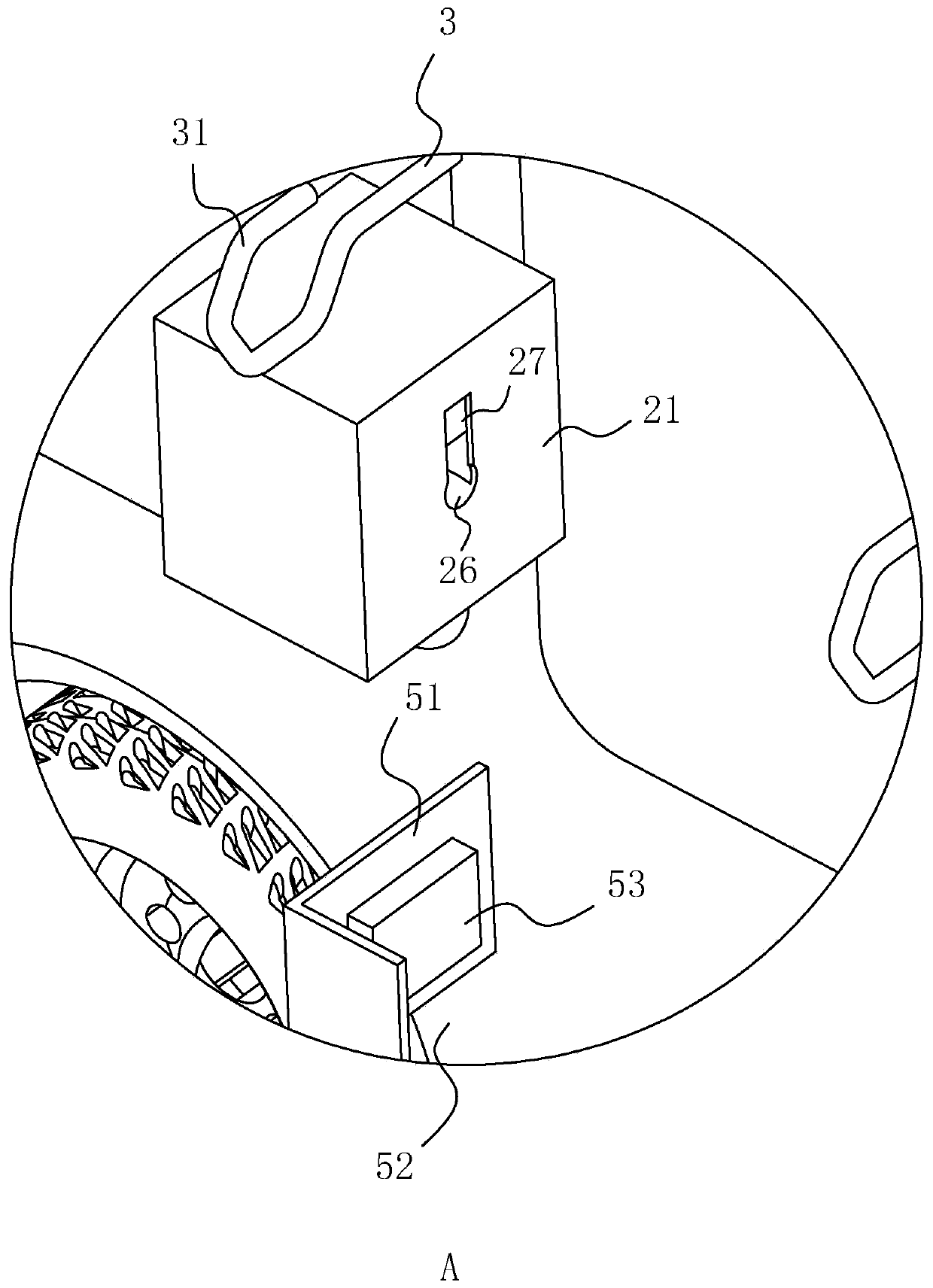
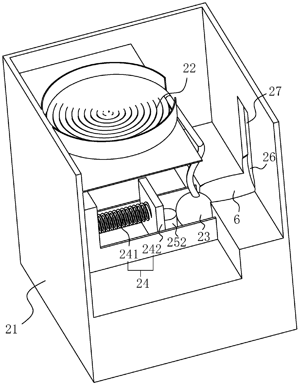
[0043] A public bus emergency escape rope ejection system, such as figure 1 As shown, a pop-up device is arranged on the side of each window 11 on the car body 1, and the ejection device 2 includes a box body 21, a stay cord 22, a force-bearing part 23, a force applying assembly 24, an opening and closing assembly 25 and a rope outlet. Mouth 26.

[0044] Such as image 3 and Figure 4 As shown, the box body 21 is fixed on the car body 1 by bolts, and the box body 21 is located in the middle of the vehicle window 11, and a supporting plate is fixed on the side wall of the box body 21 below the top wall of the box body 21. The supporting plate An accommodating cavity is formed between the top wall of the box body 21, and the drawstring 22 is accommodated in the accommodating cavity, and one end of the drawstring 22 is riveted and fixed on the support...


PUM


Abstract

The invention discloses an emergency escape rope ejection system for a public bus and aims at solving the problem that passengers in the existing public bus are easy to fall down to be injured duringjumping windows in case of an emergency. According to the key point of the technical scheme, the emergency escape rope ejection system for the public bus comprises an ejection device, a bearing assembly and a control circuit, wherein the ejection device is arranged on one side of a window and comprises a box body, a pull rope, a force bearing part, a force applying assembly, an opening and closingassembly and a rope outlet, wherein the force bearing part is fixed at the other end of the pull rope; the force applying assembly is arranged in the box body and used for ejecting the force bearingpart out of the box body; the opening and closing assembly is arranged in the box body and used for controlling the force applying assembly to apply an ejection force to the force bearing part when the window is broken; and the rope outlet is formed in the box body; the bearing assembly is arranged on the other side of the window and used for limiting the pull rope to cross over the window; and the control circuit is used for detecting the integrity of the window and controlling the opening and closing assembly to be opened when the window is broken so that the force applying assembly appliesthe ejection force to the force bearing part. The emergency escape rope ejection system for the public bus has the advantages that convenience is provided for the passengers to grab an escape rope, and falling and injuries are reduced.

Description

technical field [0001] The invention relates to the technical field of public transport emergency escape, more specifically, it relates to an emergency escape rope ejection system for public buses. Background technique [0002] With the rapid development of the economy, public transportation has become more popular, such as buses, public buses and other means of transportation have become one of the most commonly used means of transportation for people to travel. Fires caused by arson or passengers carrying inflammable and explosive materials on the bus without permission happen from time to time. When these emergencies occur, the primary task is to ensure the safe evacuation of the passengers in the bus. A fire extinguisher, but in many cases the fire extinguisher cannot completely extinguish the fire. At the same time, when a fire breaks out, the door may not be able to be opened. At this time, people can only escape by smashing the glass, but usually the windows of the bu...

Claims


Application Information

Patent Timeline
Patent Type & Authority Patents(China)
IPC IPC(8): B60R21/02
CPCB60R21/02
Inventor 唐超成黄其文
Owner 深圳市兴舞消防设备有限公司
Why Eureka
Try Eureka