Design method of honeycomb type lens array capable of improving stereo image display resolution

A technology of display resolution and lens array, applied in optical elements, optics, instruments, etc., can solve the problem that the resolution of the display cannot be fully utilized, and achieve the effect of improving imaging efficiency and resolution.

Active Publication Date: 2015-05-20
JILIN UNIV
View PDF3 Cites 7 Cited by
  • Summary
  • Abstract
  • Description
  • Claims
  • Application Information

AI Technical Summary

Benefits of technology

This technology allows for better quality images by creating an illusion between different objects being displayed on two separate screens or displays without any gaps caused when they meet at one point. It achieves this through ensuring complete continuity across all pixels within every single frame period (approximately 1) while maintaining high accuracy over time.

Problems solved by technology

Technological Problem addressed in this patents relates to improving the quality of 3D videos that use binocular techniques such as virtual shutter glass systems (VSC) due to their limited ability to perceiving depth without being tired easily. Current solutions involve combining multiple cameras together but they still result in distractedness from eye strain caused by having separate windows between each camera.

Method used


Image

  • Design method of honeycomb type lens array capable of improving stereo image display resolution
  • Design method of honeycomb type lens array capable of improving stereo image display resolution
  • Design method of honeycomb type lens array capable of improving stereo image display resolution

Examples


Embodiment Construction

[0034] The present invention will be described in detail below in conjunction with the accompanying drawings.

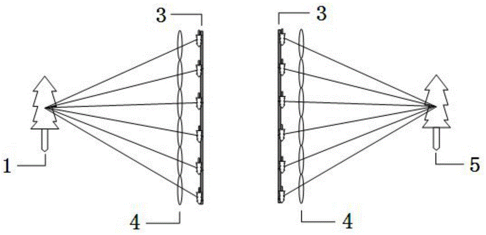
[0035] figure 2 Schematic diagram of the combined imaging system. The system mainly consists of two parts: 1, 4, 3 are the acquisition part; 3, 4, 5 are the display part. The light emitted by the real object 1 is imaged by the lens array 4 and recorded on the recording plane 3 . When displaying, the display plane 3 is placed on the focal plane of the square lens array 4, and a stereoscopic image 5 can be generated according to the principle of reversibility of the optical path.

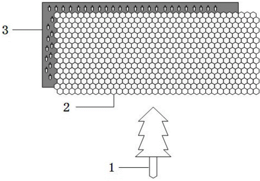
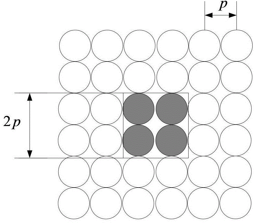
[0036] image 3 It is a schematic diagram of the structure of a square lens array, Figure 4 It is a schematic diagram of the structure of the honeycomb lens array. The pitch of the lens elements is p. In the lens array, the imaging efficiency η is defined as the effective light transmission area S of the lens array 有 with the total area S 总 The ratio of:

[0037] η = S 有 / S 总 ...


PUM


Abstract

The invention relates to a design method of a honeycomb type lens array capable of improving stereo image display resolution, and belongs to the technical field of stereo video display. The design method mainly comprises the following steps of comparing imaging efficiency, and setting a design object; performing optical design and imaging property analysis of a honeycomb type lens array formwork; matching the parameters of a display plane and the honeycomb type lens array. Compared with the traditional rectangular lens array, the method has the advantages that by adopting the honeycomb type lens array, the effective area of an optical device is sufficiently utilized, the imaging area is increased, the resolution of a stereo image is obviously improved, a high-quality three-dimensional reproductive image is obtained, and the realistic and stereo feel of watching can be improved.

Description


Claims


Application Information

Patent Timeline
Owner JILIN UNIV
Why Eureka
Try Eureka