Magnetron

一种磁控管、管接头的技术,应用在磁控管领域,能够解决浪费多、削除的材料多、紧固部件116插入困难等问题,达到减少浪费、触及良好的效果

Active Publication Date: 2015-05-20
PANASONIC INTPROP MANAGEMENT CO LTD
View PDF5 Cites 2 Cited by
  • Summary
  • Abstract
  • Description
  • Claims
  • Application Information

AI Technical Summary

Problems solved by technology

Therefore, if the cooling block 110 having the shape described in Patent Document 1 is formed by cutting a substantially rectangular parallelepiped member, there is a problem that the material to be cut increases and the waste increases.
[0012] In addition, in the state where the pipe joints 112A and 112B are connected to the cooling block 110 , sometimes it becomes difficult to insert the fastening member 116 into the through-hole 115 of the flange 114 , and it may become difficult for the parts engaged with the flange 114 Access to the fastening member 116 of the state becomes difficult

Method used


Image

  • Magnetron
  • Magnetron
  • Magnetron

Examples


Embodiment Construction

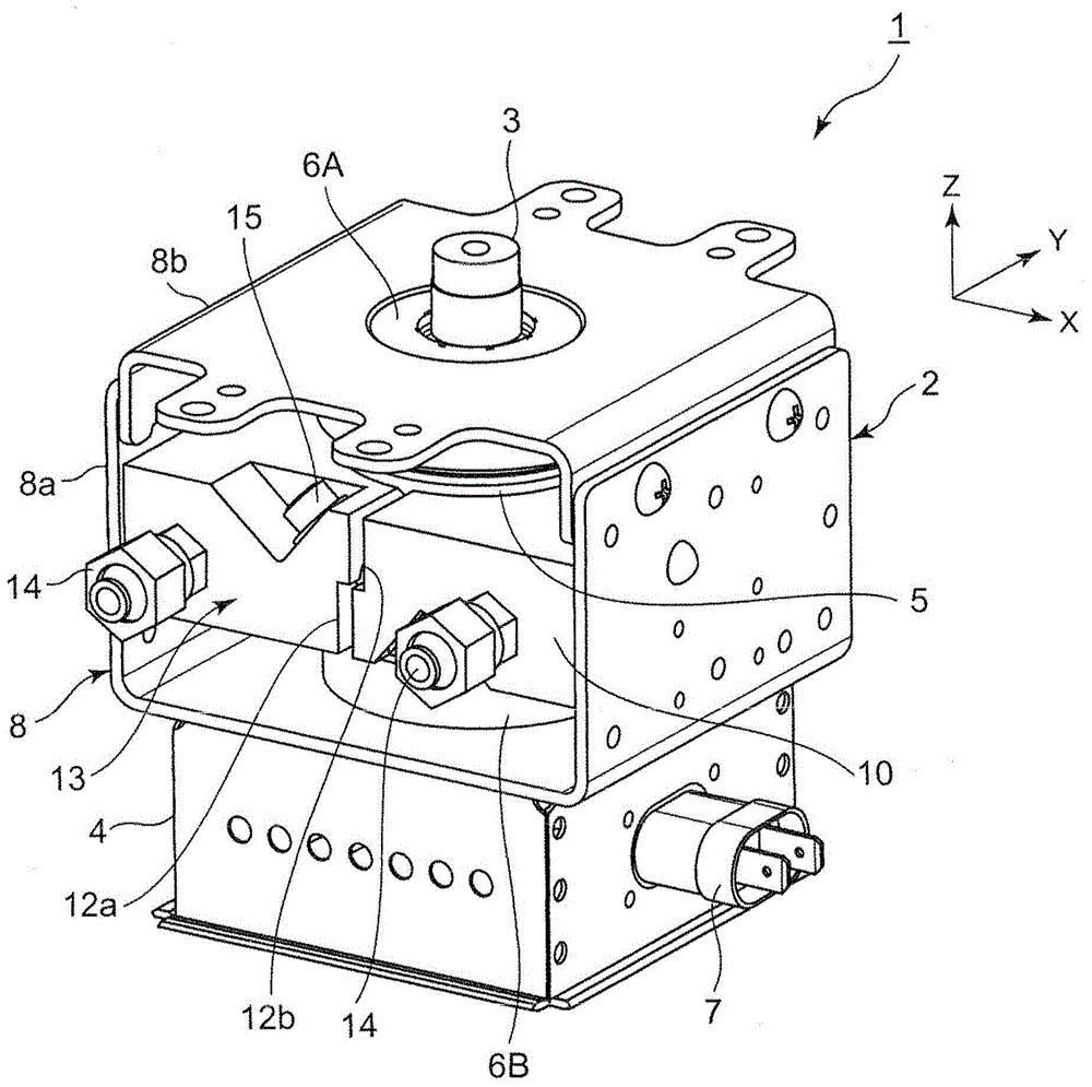
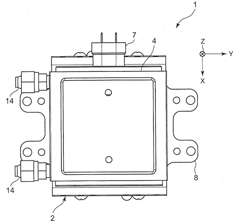
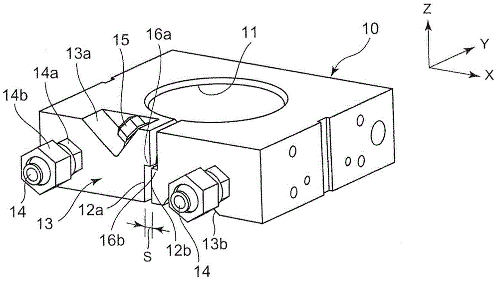
[0048] The magnetron according to the first aspect of the invention includes: an anode cylinder; and a cooling block, which is an integral part, has an annular shape in which both ends of an annular continuous portion face each other, and tightly surrounds the anode cylinder. It is fixed on the outer peripheral surface of the anode cylinder, and there is a cooling liquid circulation channel inside to cool the anode cylinder; the fastening parts are respectively engaged with the opposite ends of the cooling block, and the two ends are reduced by fastening. The distance between the ends makes the inner peripheral surface of the cooling block pressed against the outer peripheral surface of the anode cylinder; and a pair of pipe joints, which are connected to the opposite ends of the cooling block in a manner communicated with the circulation channel of the cooling liquid The adjacent parts are respectively connected, and the fastening member is arranged between a pair of pipe join...


PUM


Abstract

A magnetron includes a cooling block (10) having an annular continuous portion with opposite end portions (12a, 12b) opposed to each other, the cooling block being secured to an outer peripheral surface of the cylindrical anode body, the cooling block having a coolant circulation pathway defined therein, a tightening member (15) engageable with the opposite end portions of the cooling block to tighten the cooling block by reducing a distance between the opposite end portions of the cooling block, and a pair of pipe joints (14) each connected to a portion of the cooling block adjacent to one of the opposite end portions so as to communicate with the coolant circulation pathway. The tightening member is disposed between connecting portions of the pair of pipe joints with the cooling block so as to extend in a direction inclined with respect to a plane including an annular direction of the cooling block.

Description

technical field [0001] This invention relates to magnetrons for generating microwaves. Background technique [0002] Conventionally, magnetrons that generate microwaves have been used in magnetron-using equipment typified by microwave ovens, and magnetrons with various structures are known as their structures. As a method for removing heat generated in the magnetron due to the generation of microwaves, an air cooling type and a liquid cooling type are used. In a liquid-cooled magnetron, a cooling block provided with a cooling liquid circulation path is used (for example, refer to Patent Document 1). [0003] Here, using the diagram showing the overall structure of the magnetron Figure 9 and showing the structure of the cooling block Figure 10 The structure of the liquid-cooled magnetron described in Patent Document 1 will be described. [0004] Such as Figure 9 As shown, the magnetron 100 is provided with a cooling block 110, and the interior of the cooling block 110 i...

Claims


Application Information

Patent Timeline
Patent Type & Authority Applications(China)
IPC IPC(8): H01J1/42
CPCH01J23/005H01J25/50
Inventor 川田浩平半田贵典
Owner PANASONIC INTPROP MANAGEMENT CO LTD
Why Eureka
Try Eureka