Microphone testing method and testing system

A microphone test and microphone technology, which is applied in the field of microphones, can solve the problems of large error in test results and high cost, and achieve the effects of low cost, reduced test cost, and guaranteed accuracy

Active Publication Date: 2015-05-20
GOERTEK INC
View PDF6 Cites 12 Cited by
  • Summary
  • Abstract
  • Description
  • Claims
  • Application Information

AI Technical Summary

Benefits of technology

This technology uses two different types of microphones: one works well when they're at rest (free) while another works better on moving objects like people). By comparing these microphone responses from both devices, we can determine whether there was any difference between them. If this differences were small enough, indicating no problem during testing, the device would perform good quality tests without requiring too much space and costs more than necessary.

Problems solved by technology

This patented describes different ways to improve the accuracy of detecting tiny sounds made up from multiple components inside a device called a microscope. However, these techniques have their limitations such as requiring direct exposure to ambient environments with strong background noises, expensive equipment, complicated procedures involving building special rooms around them, etc., making it difficult to achieve consistently good levels of precision over time without any significant changes being introduced into the devices themselves due to factors like temperature fluctuations.

Method used


Image

  • Microphone testing method and testing system
  • Microphone testing method and testing system
  • Microphone testing method and testing system

Examples


Embodiment Construction

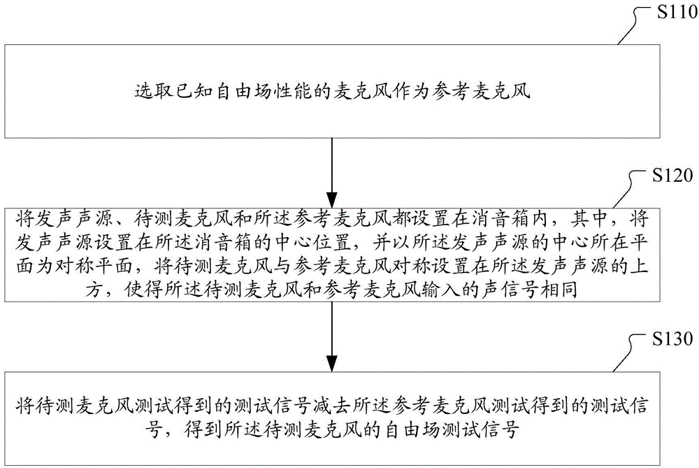
[0033] The inventive concept of the present invention is: by selecting the microphone with known free-field performance as the reference microphone, the sound source, the reference microphone, and the microphone to be tested are arranged in the muffler box, so that the sound signals input by the reference microphone and the microphone to be tested are the same, In this way, the accuracy of the test results of the microphone under test is guaranteed while reducing the test cost and the accuracy requirements for the sound source. There is no need to build a free-field test environment such as a high-cost standard anechoic chamber, and it can also ensure the accuracy of the free-field test results during the test.

[0034] figure 1 It is a flowchart of a microphone testing method provided by an embodiment of the present invention, see figure 1 , this microphone testing method of the present invention comprises:

[0035] Step S110, selecting a microphone with known free-field pe...


PUM


Abstract

The invention discloses a microphone testing method and testing system. The method comprises the following steps: selecting a microphone with known free field performance as a reference microphone; arranging a sounding source, a to-be-tested microphone and the reference microphone in a silencing box, wherein the sounding source is arranged at a central position of the silencing box, a plane where the center of the sounding source is positioned is used as a symmetric plane, and the to-be-tested microphone and the reference microphone are symmetrically arranged on the upper side of the sounding source, so input sound signals of the to-be-tested microphone and the reference microphone are the same; subtracting a test signal obtained by testing of the reference microphone from a test signal obtained by testing of the to-be-tested microphone to obtain a free field test signal of the to-be-tested microphone. The microphone testing method can guarantee the accuracy of the test result of the to-be-tested microphone, the precision requirement on the sounding source for testing is reduced, the size of the silencing box for testing is not required to be over large, and the scheme is easy to realize and low in cost.

Description


Claims


Application Information

Patent Timeline
Owner GOERTEK INC
Why Eureka
Try Eureka