
Printing spray head device based on microfluidic chip

A technology of microfluidic chip and printing nozzle, which is applied in printing and other directions, can solve the problems of mutual contamination of different materials and mixing of liquid materials, etc., and achieve the effect of small device size, low material pollution and sensitive response

Inactive Publication Date: 2015-05-27
SHENZHEN GRADUATE SCHOOL TSINGHUA UNIV
View PDF7 Cites 22 Cited by
  • Summary
  • Abstract
  • Description
  • Claims
  • Application Information

AI Technical Summary

Problems solved by technology

However, the macro-sized flow channel is prone to mixing of liquid materials, resulting in mutual contamination of different materials

Method used


Image

  • Printing spray head device based on microfluidic chip
  • Printing spray head device based on microfluidic chip
  • Printing spray head device based on microfluidic chip

Examples


Embodiment Construction

[0027] Embodiments of the present invention will be described in detail below in conjunction with the accompanying drawings. It should be emphasized that the following description is only exemplary and not intended to limit the scope of the invention and its application.

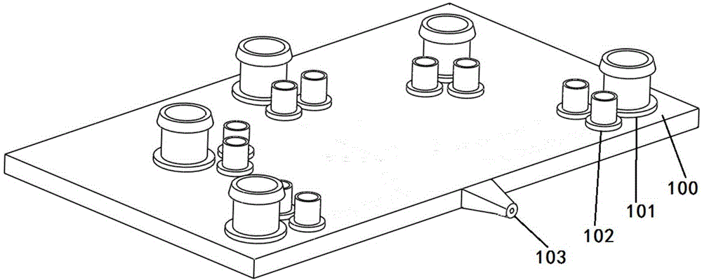
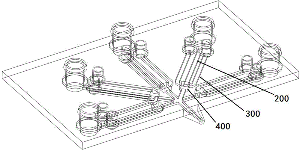
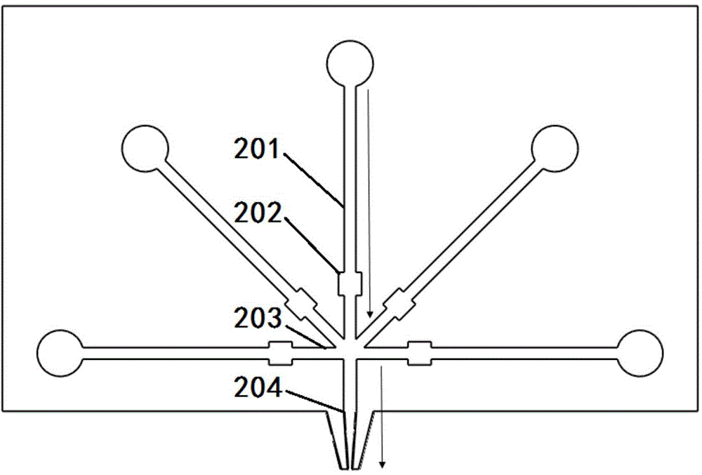
[0028] In some embodiments, the structure of the nozzle device based on the microfluidic chip is as follows: Figure 1 to Figure 7 shown. The shower head device includes a chip base 100 and a material flow channel 200 , a control flow channel 300 and a control valve 400 formed in the chip base 100 . Wherein, the control flow channel 300 intersects with the material flow channel 200 and is spatially located above the material flow channel 200 , and a control valve 400 is formed at the intersection of the two. Each flow channel is a closed structure except for the entrance and exit. In the figure, there are 5 channels for the input part of the material flow channel and the control flow channel, correspondin...


PUM


Abstract

The invention discloses a printing spray head device based on a microfluidic chip. The printing spray device comprises a chip substrate, wherein at least one material flow passage and a at least one control flow passage are formed in the chip substrate; the material flow passage is used for conveying a printing material; a fluid substance with controllable pressure flows in the control flow passage; the control flow passage and the corresponding material flow passage are intersected and a control valve is formed at an intersection; the control valve comprises a flexible film for isolating the control flow passage from the corresponding material flow passage at the intersection; the flexible film changes shape according to the pressure in the control flow passage to control connection and cutoff of the material flow passage. The printing spray device can alternately print multiple materials through a single spray head in once printing process.

Description

technical field [0001] The invention relates to a printing nozzle device based on a microfluidic chip. Background technique [0002] The goal of microfluidics is to integrate the functions of the entire laboratory on a microchip, which can be used multiple times. The device is characterized primarily by the effective structure (channels, reaction chambers, and certain other functional components) being micron-scale in at least one dimension, thereby developing unique analytical properties. It has the characteristics of controllable liquid flow, minimal consumption of samples and reagents, and increased analysis speed by ten to hundreds of times. The current key application field of work development is the field of life sciences. [0003] 3D printing (3D printing), a type of rapid prototyping technology, is a technology based on digital model files and using bondable materials such as powdered metal or plastic to construct objects by layer-by-layer printing. The method of f...

Claims


Application Information

Patent Timeline
Patent Type & Authority Applications(China)
IPC IPC(8): B41J2/14
Inventor 弥胜利徐圆圆郭潇孙伟吴啸跃钱翔
Owner SHENZHEN GRADUATE SCHOOL TSINGHUA UNIV
Learn More