A handle self-locking mechanism and folding joint

A technology for folding joints and handles, applied in the field of handle self-locking mechanisms and folding joints, can solve the problems of inconvenient operation, low locking pressure, and unreliable locking, and achieves convenient operation, simple self-locking and unlocking processes, Stable and reliable effect of locking state

Active Publication Date: 2017-03-01
深圳市富厚自行车配件有限公司
View PDF4 Cites 0 Cited by
  • Summary
  • Abstract
  • Description
  • Claims
  • Application Information

AI Technical Summary

Problems solved by technology

[0003] The existing locking mechanism relies on the pressure of the ejector rod 4' to lock the locking pin 40', which cannot guarantee the locking strength between the ejector rod and the locking pin, and can only rely on the screw rod 3' to adjust the ejector rod 4' The pressure between the locking pin and the locking pin, when the locking strength between the ejector rod 4' and the locking pin 40' is high, both locking and unlocking the locking mechanism need to rotate the screw 3' vigorously, which is extremely inconvenient to operate. When the locking strength between the ejector rod 4' and the locking pin 40' is low, the locking pressure is small and the locking is not reliable, which affects driving safety

Method used


Image

  • A handle self-locking mechanism and folding joint
  • A handle self-locking mechanism and folding joint
  • A handle self-locking mechanism and folding joint

Examples


Embodiment Construction

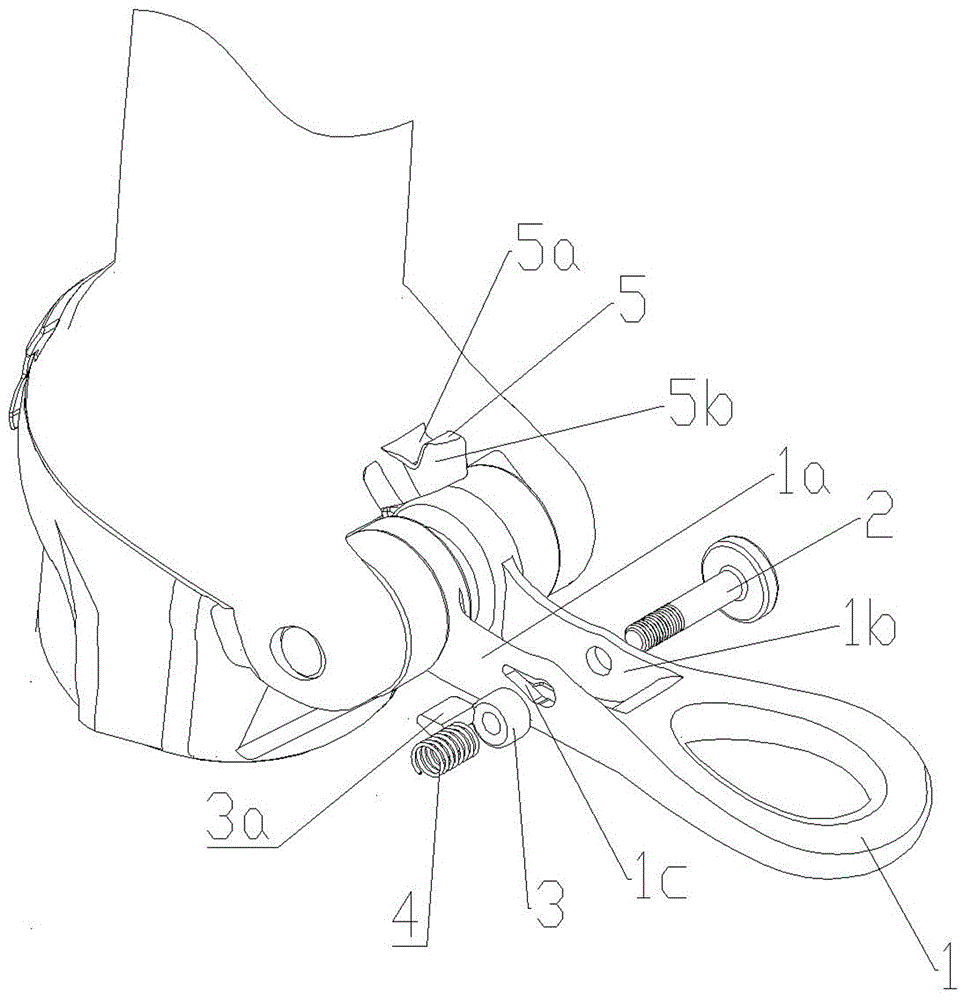
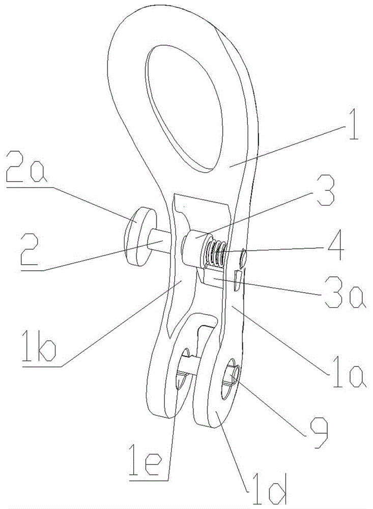
[0025] Such as figure 2 As shown, the handle self-locking mechanism proposed by the present invention includes: a handle 1, two side plates 1a, 1b symmetrically arranged in the middle of the handle 1, and locking bolts 2 that penetrate through the two side plates 1a, 1b in a movable transverse direction, and are sleeved in the lock Tighten the collar 3 and the spring 4 on the bolt 2, fix the wedge-shaped block 3a on the outer wall of one end of the collar 3, and cooperate with the locking block 5 fixed by the wedge-shaped block 3a.

[0026] Such as image 3 As shown, one side plate 1a is provided with a limit hole 1c that matches the shape of the wedge block 3a, one end of the wedge block 3a is fixed to the collar 3, and the other end movably extends into the limit hole 1c, the wedge block 3a and the collar 3 A safety hook is formed, the collar 3 is threadedly matched with the locking bolt 2, and both ends of the spring 4 are compressed between the collar 3 and the side plat...


PUM


Abstract

The invention discloses a handle self-locking mechanism. The handle self-locking mechanism comprises a handle, two side plates which are symmetrically arranged on the middle part of the handle, a locking bolt which movably and transversely penetrates through the two side plates, a sleeve ring and a spring which sleeve the locking bolt, a wedge-shaped block which is fixedly arranged on the outer wall at one end of the sleeve ring, and a locking block which is matched with the wedge-shaped block for fixing. A limiting hole which is matched with the wedge-shaped block in appearance is formed in one side plate; one end of the wedge-shaped block is fixed with the sleeve ring, and the other end of the wedge-shaped block movably stretches into the limiting hole; the sleeve ring is in threaded fit with the locking bolt, and two ends of the spring are compressed between the sleeve ring and the side plate with the limiting hole. A wedge-shaped groove which is matched with the wedge-shaped block for being occluded is formed in the locking block. The invention further discloses a folding joint with the handle self-locking mechanism. According to the handle self-locking mechanism, the locking bolt, the spring, the sleeve ring and the wedge-shaped block are arranged on the handle, and the locking block which is occluded with the wedge-shaped block is further fixed on the handle, so that an occluded state of the wedge-shaped block and the locking block can be changed by pushing the locking bolt, and the handle can be conveniently locked or unlocked.

Description

technical field [0001] The invention relates to a mechanically connected locking mechanism, in particular to a handle self-locking mechanism and a folding joint for a folding bicycle. Background technique [0002] Folding bicycles are favored by consumers for their fast folding or unfolding features. When the bicycle is folded, its volume becomes smaller, which greatly facilitates transportation and storage; after unfolding, it can be used safely, which is convenient for people to exercise or travel. The structure of the handle locking mechanism used in general folding bicycles on the market is as follows: figure 1 As shown, the locking mechanism includes a handle 1', a nut pin 2' located on the upper part of one side of the handle, a push rod 4' connected to the screw hole of the nut pin through an upper end screw rod 3', and the lower end of the push rod passes through the device. The guide hole of the guide seat 5' at the bottom of the handle 1'. The lower end of the h...

Claims


Application Information

Patent Timeline
Patent Type & Authority Patents(China)
IPC IPC(8): B62K15/00
Inventor 胡明欧玉田
Owner 深圳市富厚自行车配件有限公司
Why Eureka
Try Eureka