Limiting tool frame and limiting tool

A tooling frame and position-limiting technology, which is applied in the direction of transportation and packaging, containers and containers to prevent mechanical damage, etc., can solve the problems of inability to adapt to the general requirements of packaging for variety appearance differences, high overall cost of tooling frames, poor universality of tooling frames, etc. , to achieve the effect of preventing mutual scratches and scratches, simple structure, and not easy to damage parts

Active Publication Date: 2015-05-27
GREE ELECTRIC APPLIANCES INC
View PDF6 Cites 5 Cited by
  • Summary
  • Abstract
  • Description
  • Claims
  • Application Information

AI Technical Summary

Problems solved by technology

[0002] In the prior art, most of the various tooling racks are designed as partitions with fixed structures. In this way, the tooling racks have poor versatility and single purpose, and cannot meet the general requirements of material packaging with many varieties and large differences in shape.
It is necessary to design tooling racks with different structural forms, and the number of tooling racks is various, which leads to high overall cost of purchasing tooling racks and is easy to cause idle

Method used


Image

  • Limiting tool frame and limiting tool
  • Limiting tool frame and limiting tool
  • Limiting tool frame and limiting tool

Examples


Embodiment Construction

[0036] In order to solve the problem of poor versatility of logistics tooling racks, a limited tooling rack suitable for different sizes of transportation logistics is proposed to achieve higher versatility and diversification of uses.

[0037] The above and other technical features and advantages of the present invention will be described in more detail below in conjunction with the accompanying drawings.

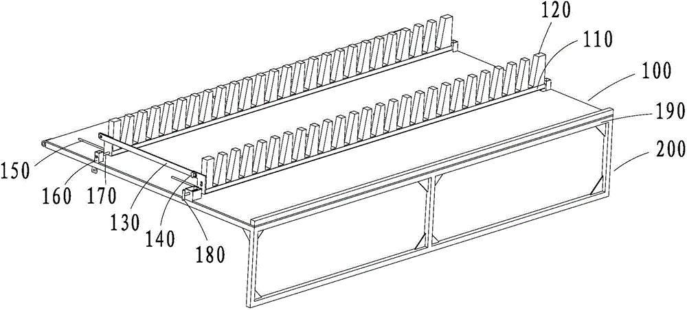
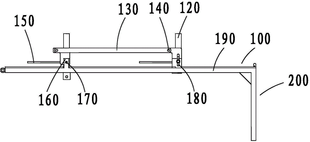
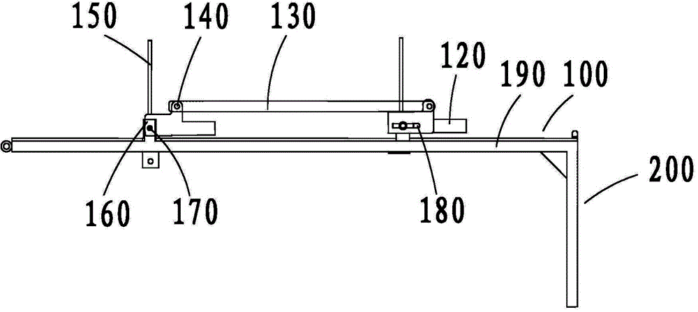
[0038] see figure 1 As shown, it is a partial three-dimensional schematic diagram of the position-limiting tool of the present invention. The position-limiting tool frame 100 includes a position-limiting bar 110 , a spacer bar 120 , a connecting rod 130 and a positioning layer 190 .

[0039] The number of limiting strips 110 is at least two, which is the same as the number of limiting spacers 120; in this embodiment, two limiting strips 110 are provided. A limiting spacer 120 is fixed on each limiting bar 110 .

[0040] The spacer bar 120 is a flat plate with continuous ...


PUM


Abstract

The invention relates to a limiting tool frame and a limiting tool. The limiting tool frame comprises a positioning layer, at least two limiting strips, at least two limiting separating strips, and a connecting rod; one limiting separating strip is fixed on each limiting strip; each limiting separating strip is a flat plate, and continuous teeth are arranged in one side edge; the limiting strips are mounted on the positioning layer; the connecting rod is connected with all limiting separating strips through a connecting shaft; the connecting rod drives all limiting separating strips to rotate. The limiting tool comprises a plurality of limiting tool frames and a plurality of supporting frames; the supporting frames are vertical to positioning layers of the limiting tool frames; the plurality of limiting tool frames can be supported by layers; therefore, purposes of improving the generality and diversifying the purposes can be reached.

Description

technical field [0001] The invention relates to the field of logistics tooling, in particular to a logistics tooling suitable for box-free transportation of large-sized parts such as household appliances and automobiles. Background technique [0002] In the prior art, most of the various tooling racks are designed as partitions with fixed structures. In this way, the tooling racks have poor versatility and single purpose, and cannot meet the general requirements of material packaging with many varieties and large differences in shape. It is necessary to design tooling racks with different structural forms, and there are many varieties of tooling racks, which leads to high overall cost of purchasing tooling racks and is easy to cause idleness. [0003] In view of the above-mentioned defects, the inventor has finally obtained the present invention through long-term research and practice. Contents of the invention [0004] Based on this, it is necessary to provide a position...

Claims


Application Information

Patent Timeline
Patent Type & Authority Applications(China)
IPC IPC(8): B65D25/10B65D81/05
Inventor 陈亮孙超余清山肖学良钟明生陈斌蒙伟莲
Owner GREE ELECTRIC APPLIANCES INC
Why Eureka
Try Eureka