
Electrical equipment connector lead temperature measuring device prepared by adopting fusible alloy

A technology of fusible alloys and electrical equipment, applied in measuring devices, thermometers with physical/chemical changes, thermometers, etc., can solve problems such as inconvenient pasting, inconsistent bonding areas, and easy misleading, so as to achieve obvious warning effects and avoid Time-consuming and labor-intensive, accurate fault heating effect

Active Publication Date: 2015-05-27
STATE GRID CORP OF CHINA +1
View PDF4 Cites 5 Cited by
  • Summary
  • Abstract
  • Description
  • Claims
  • Application Information

AI Technical Summary

Problems solved by technology

The disadvantages of using temperature-indicating wax sheets are as follows: first, special equipment is needed to paste the temperature-indicating wax sheets with electricity, and it is inconvenient to paste; Consistent, it can also melt under the sunlight in summer, and it is impossible to test the heat generated by the fault caused by the natural heating of the row, which is easy to cause misleading, inconvenient observation, and the warning effect is easy to be ignored. It is pasted at the intersection of the substation equipment joints, so the paste is not firm, and the bonding area is inconsistent, which affects the temperature measurement effect; Fourth, the temperature-indicating wax sheet is pasted on the wire joint, not on the wire, so the temperature of the wire cannot be directly tested
[0004] It can be seen from the search that there is no report on a temperature measuring device for electrical equipment joint wires that uses fusible alloys as temperature testing materials and can be assembled and disassembled while live.

Method used


Image

  • Electrical equipment connector lead temperature measuring device prepared by adopting fusible alloy

Examples


Embodiment Construction

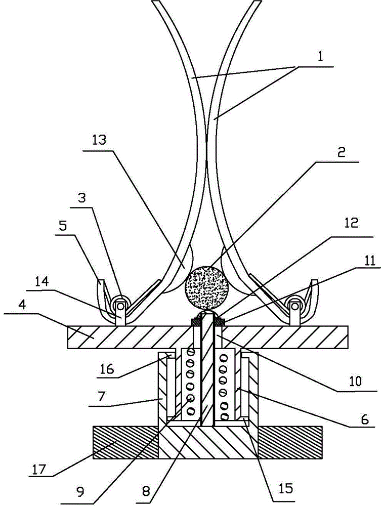
[0016] The temperature measuring device for electrical equipment joint wires made of fusible alloys includes an arc-shaped elastic clip 1, and the arc-shaped elastic clip 1 is provided with two left and right pieces, and the middle parts of the left and right two arc-shaped elastic clips 1 are opposite to each other. Contact, the upper openings of the left and right arc-shaped elastic clips 1 are snapped into the electrical equipment connector wire 2 through the upper openings of the left and right arc-shaped elastic clips 1, characterized in that: the left and right The lower ends of the two arc-shaped elastic clips 1 are provided with a semicircular curved section 5, and a coil spring 3 for clamping the lower ends of the left and right two arc-shaped elastic clips 1 is arranged in the semicircular curved section 5. The shaft end of the spring 3 is fixed to the circular seat plate 4 through the support plate 14, and the lower end of the left and right arc-shaped elastic clips ...


PUM

PropertyMeasurementUnit
melting pointaaaaaaaaaa

Abstract

The invention discloses an electrical equipment connector lead temperature measuring device prepared by adopting a fusible alloy. The electrical equipment connector lead temperature measuring device comprises a left arc elastic clamping piece and a right arc elastic clamping piece. The electrical equipment connector lead temperature measuring device is characterized in that semi-circular curved sections of the lower ends of the arc elastic clamping pieces are both provided with coil springs enabling lower end clamping openings of the left and right arc elastic clamping pieces to be clamped tightly; the middle of a base plate surface of a round seat plate is provided with an overtemperature sign cylinder the outer side of which is sleeved by a cylindrical seal cap; the center of the cylindrical seal cap is provided with a core rod sleeved with a compression spring; the part, passing through a central through hole of the round base plate, of the core rod is sleeved with a fusible alloy ring; a heat conduction screw cap is screwed tightly on the upper end of the core rod. The device can be installed under the condition that a high-voltage power transformation device runs with power, furthermore, because the fusible alloy is adopted as a temperature test material, the device has the advantages of accurate fuse point, narrow range, response sensitivity and short fuse time; moreover, the fuse point can be adjusted according to seasons, the influences by natural temperature rise can be eliminated, and the fault temperature rise can be judged more accurately; the device is easy to install, is flexible and convenient to use, and has an obvious warning effect.

Description

technical field [0001] The invention relates to an improvement of a temperature measuring device for a joint of electrical equipment, in particular to a temperature measuring device for a lead wire of an electrical equipment joint made of a fusible alloy, which can replace a temperature-indicating wax sheet and has more stable performance. Background technique [0002] The heating of electrical equipment joints in substations is a frequent fault, which occurs frequently due to environmental factors, joint design, improper installation and maintenance processes and other reasons. When the power grid is facing peak summer and winter peaks, and the load current is relatively large, electrical equipment joint heating faults are more likely to occur. If the heating fault of the equipment joint exists for a long time without being discovered, it may cause a power outage of the equipment, or even damage the equipment. Therefore, timely detection of hot spots and timely elimination...

Claims


Application Information

Patent Timeline
Patent Type & Authority Applications(China)
IPC IPC(8): G01K11/06
Inventor 杜洪涛李山冈胡昌伦
Owner STATE GRID CORP OF CHINA
Learn More