Power supply circuit for dynamic redundancy control

A power supply circuit, dynamic redundancy technology, applied in general control systems, control/regulation systems, instruments, etc., can solve problems such as cost sensitivity, redundancy, and large PCB space occupation, to ensure reliability and safety, reduce The effect of volume and cost reduction

Inactive Publication Date: 2015-05-27
XIAN KEYWAY TECH
View PDF8 Cites 5 Cited by
  • Summary
  • Abstract
  • Description
  • Claims
  • Application Information

AI Technical Summary

Problems solved by technology

[0004] In this method, the reliability of the power supply in each loop is proportional to the number of relays; when there are multiple power supply outputs in the control loop, multiple relays are required, which takes up a lot of PCB space and is expensive, and is not suitable for the PCB area. Occasions that are limited, cost-sensitive and need to ensure power supply reliability
[0005] In addition, this method has a fixed redundancy for each channel, once connected, it cannot be changed
Even if the relays of one channel are faulty and the relays of the other channel are all normal, the normal relays cannot separate their own backup relays to take over the work of the faulty relays, and cannot fully play the role of redundancy
In addition, when one of the channels is faulty or the load is short-circuited and open-circuited, it cannot be identified and recorded, and fault diagnosis cannot be performed.

Method used


Image

  • Power supply circuit for dynamic redundancy control
  • Power supply circuit for dynamic redundancy control
  • Power supply circuit for dynamic redundancy control

Examples


Embodiment 1

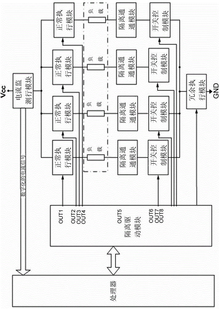
[0026] Such as figure 2 As shown, this embodiment takes 4-way loads as an example, and the dotted line box shows 4-way loads, indicating the position of the loads in the circuit of the present invention, which does not belong to the circuit itself.

[0027] In this embodiment, the power supply circuit of the dynamic redundancy control is composed of a processor, an isolation drive module, 4 normal execution modules, 4 loads, 4 isolation modules, 4 switch control modules, a redundant execution module and a monitoring Module composition.

[0028] Wherein the processor is respectively connected with the isolation driving module and the monitoring module.

[0029] The isolation drive module is respectively connected with each normal execution module, switch control module and redundant execution module.

[0030] Each normal execution module is connected to a load.

[0031] Each load is also connected in turn with an isolation module, a switch control module and a redundant exe...


PUM


Abstract

The invention relates to a technology of dynamic redundancy output implementing power supply control and safety design, in particular to a power supply circuit for dynamic redundancy control. The power supply circuit comprises a plurality of normal execution modules, a switch control module, a redundancy execution module and a monitoring module, wherein each normal execution module comprises a relay, and the redundancy execution module comprises a relay; the monitoring module comprises a circuit parameter detection device and a detection signal analysis and judgment device, which are connected with each other; the circuit parameter detection device monitors the circuit parameters of the normal execution modules during working and transmits a detection result to the detection signal analysis device, the detection signal analysis device analyzes and judges the signal to generate a command and sends the command to the switch control module, and the switch control module is switched on and switched off according to the command; the switch control module comprises a switching device which is connected with the redundancy execution module and the detection signal analysis and judgment device. According to the power supply circuit, the cost can be effectively reduced, the size of a circuit board is reduced, and a certain reliability and safety are ensured.

Description

technical field [0001] The invention relates to a technique for implementing power supply control and safety design with dynamic redundant output, and is especially used in occasions where reliability is high, PCB area is small, and cost is sensitive. Background technique [0002] At present, the commonly used power supply control scheme is: first output high and low levels from different output ports of the processor or programmable device, and drive different relays to operate after isolation and drive enhancement through optocouplers. Due to the structural characteristics of the relay, failures are most likely to occur during use. Therefore, in the known methods, static redundant outputs are generally used to realize power supply control. That is, the relay is used as the control actuator, and the two relays jointly complete the output control of one power supply, forming a redundant design. Specifically, it is to connect the output ends of the relays controlled by two o...

Claims


Application Information

Patent Timeline
IPC IPC(8): G05B9/03
Inventor 魏志鹏何健
Owner XIAN KEYWAY TECH
Why Eureka
Try Eureka