Electrical pyrotechnic switch

An electrical switch, pyrotechnic technology, applied in the field of electrical switches, which can solve problems such as high ignition, damage or loss of connection

Active Publication Date: 2015-05-27
AUTOLIV DEV AB
View PDF4 Cites 5 Cited by
  • Summary
  • Abstract
  • Description
  • Claims
  • Application Information

AI Technical Summary

Problems solved by technology

In fact, the deflected surface of the slider will contact the terminal through a line or a simplified surface, and any high current will arc or will heat the material located at the contact line, with a high risk of ignition, damage or loss. connection risk

Method used


Image

  • Electrical pyrotechnic switch
  • Electrical pyrotechnic switch
  • Electrical pyrotechnic switch

Examples


Embodiment Construction

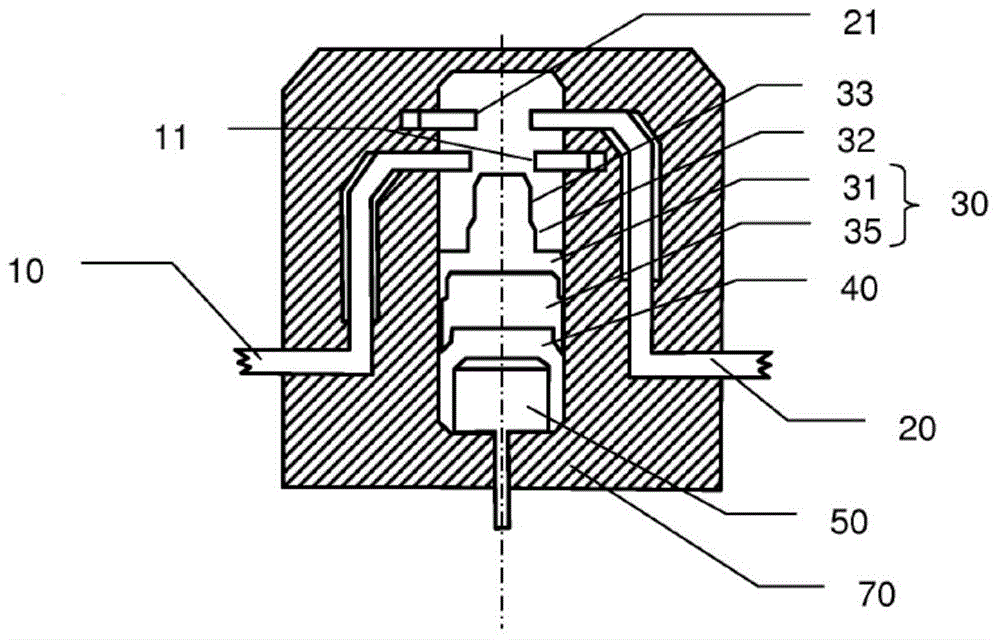
[0049] figure 1 The electrical switches shown include:

[0050] - a first conductive terminal 10 with a first cylindrical contact portion 11,

[0051] - a second conductive terminal 20 comprising a second cylindrical contact portion 21,

[0052] - a movable body 30 having a first cylindrical contact surface 32 and a second contact surface 33 arranged on the conductive part 31 ,

[0053] - a combustion chamber 40 closed by said movable body 30,

[0054] - an electro-pyrotechnic device 50 arranged to generate pressurized gas in the combustion chamber 40,

[0055] The movable body 30 is made of two parts, a conductive part 31 and an insulating part 35 .

[0056] The first contact portion 11 exhibits a larger cross-section than the second contact portion 21 , and correspondingly, the first contact surface 32 exhibits a larger cross-section than the second contact surface 33 . This arrangement ensures that the first contact portion 11 does not contact the second contact surfac...


PUM


Abstract

Electrical switch comprising: - a first conductive terminal comprising a first contact portion, - a second conductive terminal comprising a second contact portion, - a moveable body moveable from a first position, in which the first and second contact portions are electrically disconnected, to a second position, in which the first and second contact portions are electrically connected, characterized: - in that said first and second contact surfaces are cylinders parallel to respectively said first and second contact portions, - in that the second contact surface freely goes through the first contact portion, - in that the first contact surface enters in connection with the first contact portion simultaneously to the moment when the second contact surface enters in connection with the second contact portion, - and in that at least one of said first and second surfaces and the corresponding one of the first and second contact portions are arranged so that the moveable body is maintained in the second position.

Description

technical field [0001] The present invention relates to an electrical switch, and in particular to an electrical switch controlled to be actuated by a pyrotechnic device. Background technique [0002] Document WO 2011 / 064510 A1 describes an electrical switch actuated by a pyrotechnic device. One of the disclosed embodiments is a switch comprising three conductive terminals, and the slider is movable from a first position (wherein two of these terminals are disconnected) to a second position (wherein these two terminals are electrically connected ). However, since the slider connects one of the two terminals to the third in said first position, the movement of the slider requires a lot of force. It takes a lot of force to sever this initial connection. Such a large effort could either cause functional problems (if the pyrotechnic device does not provide enough energy to push the slide), or a powerful and expensive pyrotechnic device would be necessary to ensure reliable fu...

Claims


Application Information

Patent Timeline
Patent Type & Authority Applications(China)
IPC IPC(8): H01H39/00
CPCH01H39/004
Inventor 布伦特·帕克斯阿米娜·哈米达帕特里斯·布坦阿兰·马涅
Owner AUTOLIV DEV AB
Why Eureka
Try Eureka