
Tunnel support installation apparatus

A technology in tunnels and tunnels, used in tunnels, tunnel linings, shaft equipment, etc., can solve problems such as cracks

Inactive Publication Date: 2017-03-22
SANDVIK INTELLECTUAL PROPERTY AB
View PDF11 Cites 10 Cited by
  • Summary
  • Abstract
  • Description
  • Claims
  • Application Information

AI Technical Summary

Problems solved by technology

In particular, components of the mining machine frame or components of the motor often break due to stress concentrations when supporting the considerable weight of the manipulator assembly

Method used


Image

  • Tunnel support installation apparatus
  • Tunnel support installation apparatus
  • Tunnel support installation apparatus

Examples


Embodiment Construction

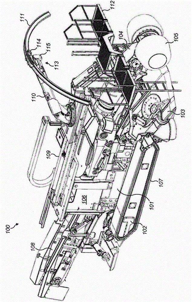
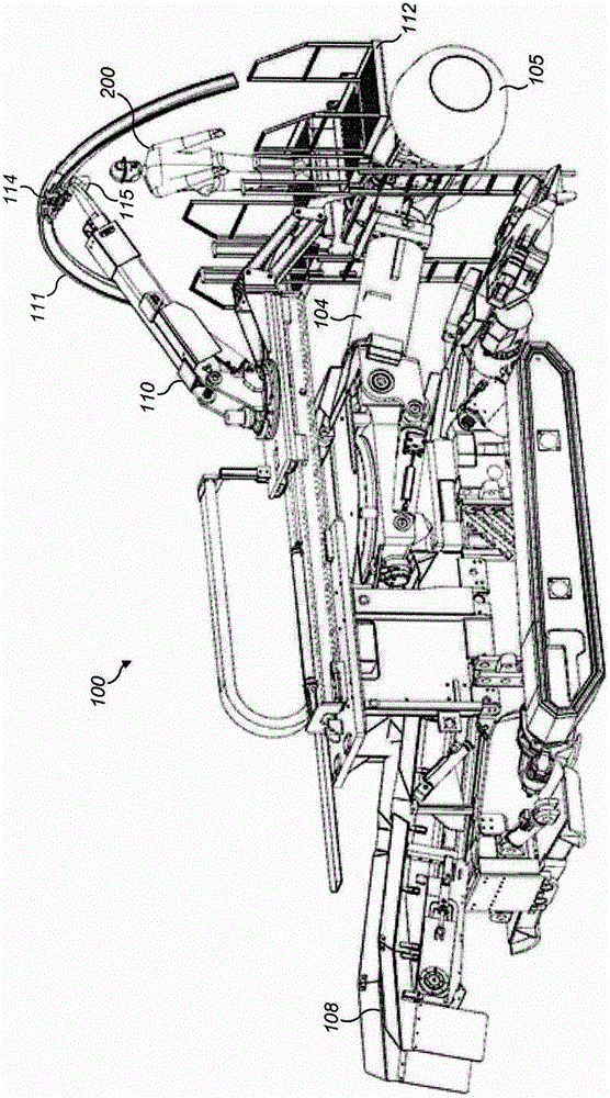
[0035] refer to figure 1 and 2 , the mobile mining machine 100 includes a main frame 101 , and the main frame 101 is equipped with a pair of crawler belts 107 through a chassis 102 . A motor 106 is also carried by the main frame 101 and is located generally centrally on the body of the mining machine 100 . A rotatable cutting head, generally indicated by reference numeral 105, is located at the front end of the mining machine 100 and includes a plurality of drums that mount a plurality of cutting bits (not shown). The head 105 is mounted on the main frame 101 by means of an elongated beam 104, and the elongated cantilever 104 is pivotally mounted to the main frame 101 at its rear end. Rake fingers 103 are also mounted at the front end of the mining machine below boom 104 to receive and collect material dislodged from the cutting face. The mining machine 100 also includes a discharge conveyor 108 extending rearwardly from the claws 103 and protruding rearwardly from the mini...


PUM


Abstract

Apparatus to install structural supports in a mine tunnel. The apparatus is conveniently mountable on a mining machine having a cutting head (105) mounted at one end of a cantilever. An extendable and slewing manipulator arm (110) is mounted on a support platform that is slidable in the axial forward and rearward direction and comprises a grasping device to hold the structural supports (111) in a plurality of different positions.

Description

technical field [0001] The present invention relates to an apparatus for installing structural support in a mine tunnel and in particular, but not exclusively, to a mining machine mounted assembly having an extendable arm , to transport and hold supports for attachment to the tunnel roof or walls. Background technique [0002] Mobile mining machines have been developed to provide direct cutting of rock faces as well as rapid road and tunneling within mines. Typically, mobile tunnel boring machines include a rotatable cutting head with a drill bit on a rotating drum to break up the rock face. The cutting head is mounted on a movable boom to create a tunnel with the required width and height. As the cutting head is rotated and advanced into the surface, the mined material is collected by gathering heads and conveyed back through the mining machine mounted conveyor. [0003] To keep the tunnel safe while the mining machine is advancing, a framework of beams, arches or mesh i...

Claims


Application Information

Patent Timeline
Patent Type & Authority Applications(China)
IPC IPC(8): E21C27/24E21D11/18E21D11/40
CPCE21D11/403E21C25/10E21C27/24E21D11/18
Inventor 扬·斯特茨马雷克·索哈
Owner SANDVIK INTELLECTUAL PROPERTY AB
Learn More