

Aircraft electric braking system
一种飞行器、电动制动的技术,应用在制动控制系统、飞机制动安排、制动器等方向,能够解决制动控制丧失、丧失等问题,达到减轻重量、增强可靠性、节约成本的效果
- Summary
- Abstract
- Description
- Claims
- Application Information
AI Technical Summary
Problems solved by technology
Method used
Image

Examples
Embodiment Construction
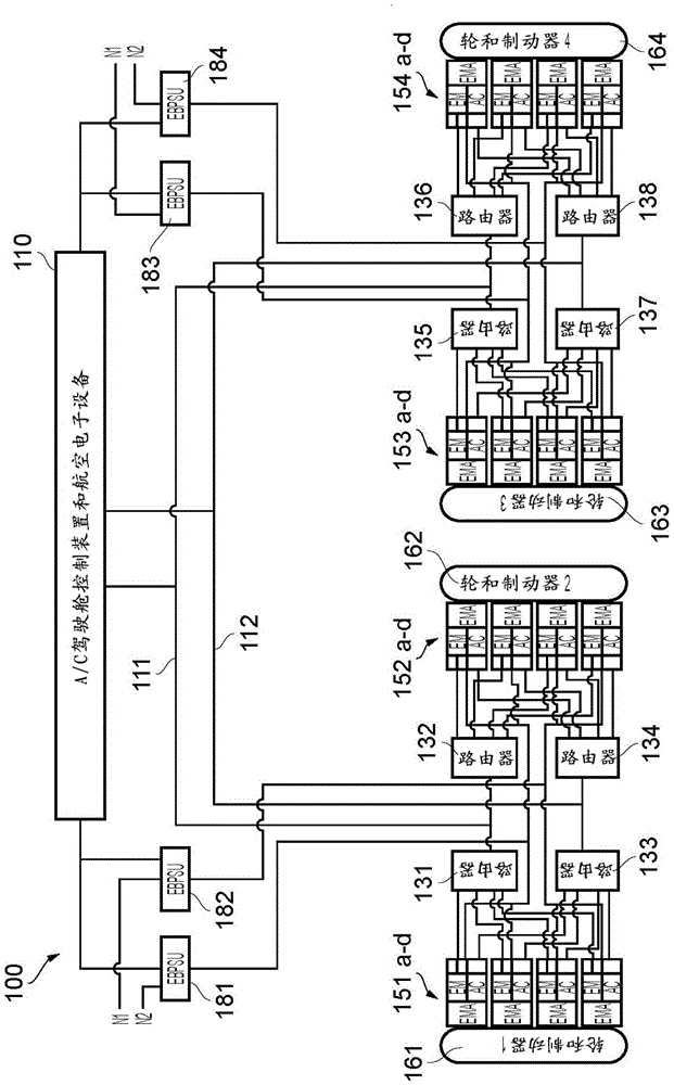
[0044] exist figure 1 The illustrated first embodiment electric aircraft braking system 100 is configured for use with an aircraft having two braked main landing gear, one of which is on either side of the centerline of the aircraft. However, it will be appreciated that the invention described herein relates to any aircraft configuration having braked wheels, including aircraft having more than two main landing gear and / or braked nose landing gear. The braking system 100 features fully distributed avionics.
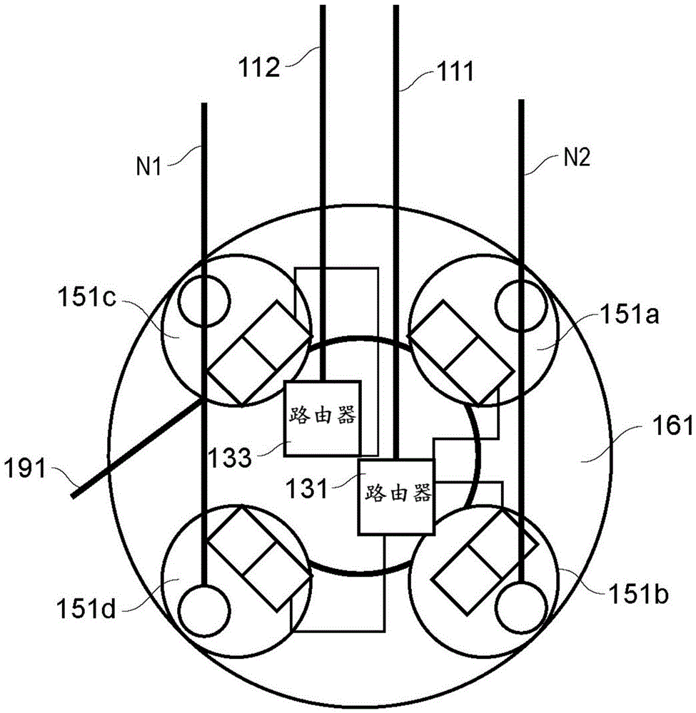
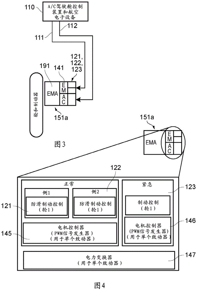
[0045] Braking system 100 includes aircraft cockpit controls and avionics 110, which communicate via data buses 111, 112 and routers 131 to 138 with "fully intelligent" electromechanical brake actuators (EMA) 151a-d, 152a-d , 153a-d, and 154a-d (described in detail below), the "fully intelligent" electromechanical brake actuators (EMA) 151a-d, 152a-d, 153a-d, and 154a-d communicate with the wheel and brake sets 161 to 164 are associated. In this example, there are four...
PUM
 Abstract
Description
Claims
Application Information