
Wheel pressure balance mechanism for crane cab

A technology of balancing mechanism and crane, which is applied in the direction of traveling mechanism, load hanging components, transportation and packaging, etc. It can solve the problems of fast friction of the guide rail group, large wheel pressure, deformation of the guide rail group, etc., and achieve the effect of avoiding deformation

Inactive Publication Date: 2015-06-03
SICHUAN FEDSTORE TECH
View PDF0 Cites 0 Cited by
  • Summary
  • Abstract
  • Description
  • Claims
  • Application Information

AI Technical Summary

Problems solved by technology

[0002] When the commonly used cranes are in use, since three points determine a common plane, in the worst case, three sets of wheel sets bear the weight of the crane cab, resulting in excessive wheel pressure, which makes the guide rail set easy to deform or the wheel set and The wear of the guide rail set is faster
In addition, if the wheel set does not touch the guide rail set when moving, it will cause the lifting cab to have no power and the movement is not smooth, and produce unpleasant noises

Method used


Image

  • Wheel pressure balance mechanism for crane cab
  • Wheel pressure balance mechanism for crane cab
  • Wheel pressure balance mechanism for crane cab

Examples


Embodiment Construction

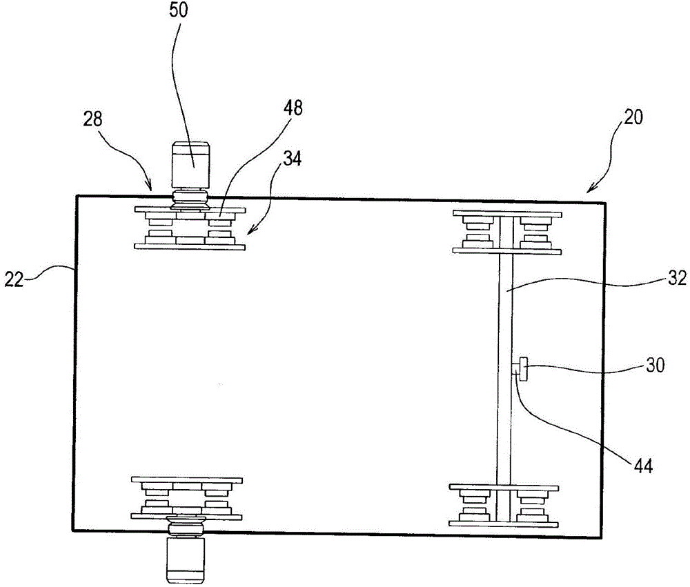
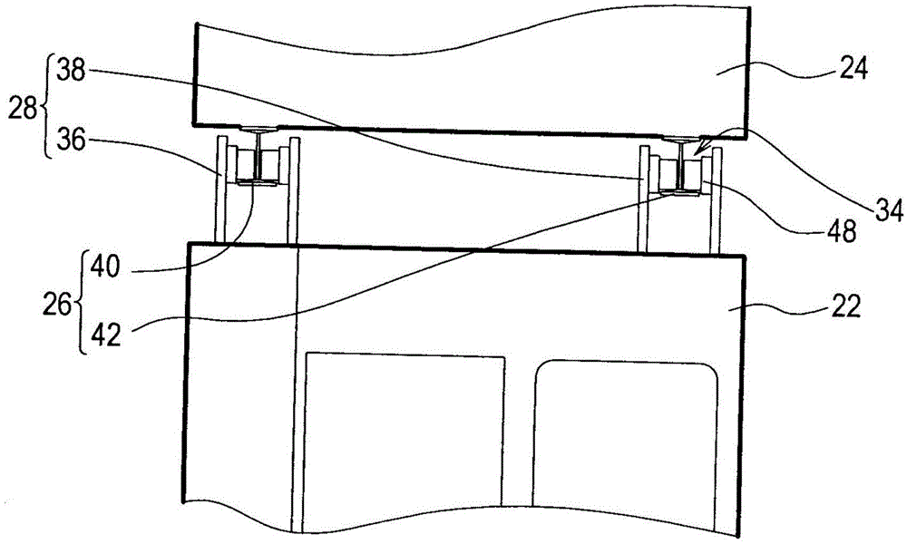
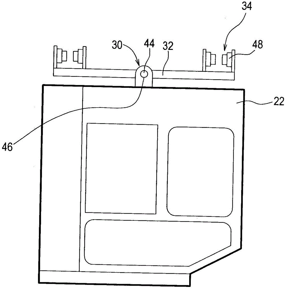
[0011] The wheel pressure balance mechanism 20 of the crane cab is applied to a guide rail set 26 for suspending a crane cab 22 below a crane girder 24 . Wherein the crane cab 22 can be configured on a ship unloader or the like. The wheel pressure balancing mechanism 20 of the crane cab includes a plurality of wheel set fixing seats 28 , a balance bar fixing seat 30 , a first balance bar 32 and a plurality of wheel sets 34 . The wheel set fixing base 28 and the balance bar fixing base 30 are all arranged on the top of the crane cab 22, and the wheel set fixing base 28 corresponds to the guide rail set 26, wherein the wheel set fixing base 28 includes a first wheel set fixing base 36 and a first wheel set fixing base 36. The two wheel set fixing seats 38, and the guide rail set 26 include a first guide rail 40 and a second guide rail 42 parallel to each other. The first wheel set fixing seat 36 and the second wheel set fixing seat 38 correspond to the first guide rail 40 and t...


PUM


Abstract

The invention discloses a wheel pressure balance mechanism for a crane cab. The wheel pressure balance mechanism comprises a plurality of wheel group fixing seats, a balance rod fixing seat, a first balance rod and a plurality of wheel groups, wherein the wheel group fixing seats are arranged above the crane cab and correspond to a guide rail group; the guide rail group comprises a first guide rail and a second guide rail; the first guide rail is parallel to the second guide rail; the balance rod fixing seat is arranged above the crane cab; the center of the first balance rod is movably connected to the balance rod fixing seat; each wheel group is provided with at least one wheel; all the wheel groups are respectively arranged on all the wheel group fixing seats and at the two ends of the first balance rod; the crane cab is suspended on the guide rail group through the wheel groups and is driven by at least one driving motor to move below a crane main beam; the wheel group fixing seats and the balance rod fixing seat are arranged on one plane, and the first balance rod is movably connected to the balance rod fixing seat. According to the wheel pressure balance mechanism, the phenomena that the known guide rail group is easily deformed, the wheel groups and the guide rail group are rapider in abrasion, the crane cab often cannot get power instantly and cannot move smoothly to generate unpleasant noise can be avoided.

Description

technical field [0001] The invention relates to a balance mechanism, in particular to a wheel pressure balance mechanism of a crane cab. Background technique [0002] When the commonly used cranes are in use, since three points determine a common plane, in the worst case, three sets of wheel sets bear the weight of the crane cab, resulting in excessive wheel pressure, which makes the guide rail set easy to deform or the wheel set and The wear of the rail set is faster. In addition, if the wheel set does not touch the guide rail set when moving, it will cause the lifting cab to have no power and the movement is not smooth, and produce unpleasant noises. Contents of the invention [0003] The technical problem to be solved by the present invention is to overcome the defects of the prior art and provide a wheel pressure balance mechanism for a crane cab. [0004] The technical solution adopted to solve the above technical problems is: a wheel pressure balance mechanism of a...

Claims


Application Information

Patent Timeline
Patent Type & Authority Applications(China)
IPC IPC(8): B66C9/12B66C13/54
CPCB66C9/12B66C13/52
Inventor 蒲思羽
Owner SICHUAN FEDSTORE TECH
Learn More