A kind of fiber cage for loose fiber dyeing machine

A dyeing machine and fiber cage technology, applied in the direction of processing textile material carriers, etc., can solve the problems of easy extrusion damage to the cylinder, damage to the dye vat, bumps, etc., to achieve convenient maintenance and repair, reduce direct collisions, and improve service life. Effect

Inactive Publication Date: 2016-08-17
吴江市佳福纺织有限公司
View PDF2 Cites 0 Cited by
  • Summary
  • Abstract
  • Description
  • Claims
  • Application Information

AI Technical Summary

Problems solved by technology

[0002] In the existing loose fiber dyeing machine, the fiber cage is hoisted into the dyeing vat, and there is no buffer device at the bottom of the dyeing vat, so that when the fiber cage is placed into the dyeing vat, it will collide with the dyeing vat, causing the dyeing vat to be damaged. At the same time, the existing There is a cylinder inside the fiber cage to ensure that the nozzle can be inserted into the cylinder for spraying, and the fiber material will not block the middle of the fiber cage. The cylinder is easy to be squeezed and damaged. After damage, the fiber needs to be removed Cage replacement, high cost of fiber cage replacement

Method used


Image

  • A kind of fiber cage for loose fiber dyeing machine
  • A kind of fiber cage for loose fiber dyeing machine

Examples


Embodiment Construction

[0014] The present invention will be described in detail below in conjunction with accompanying drawings and specific preferred embodiments, so that the advantages and features of the present invention can be more easily understood by those skilled in the art. range is limited.

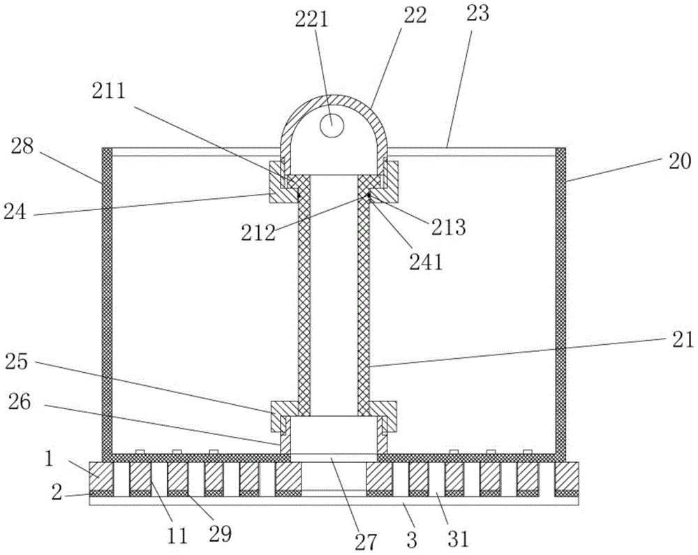
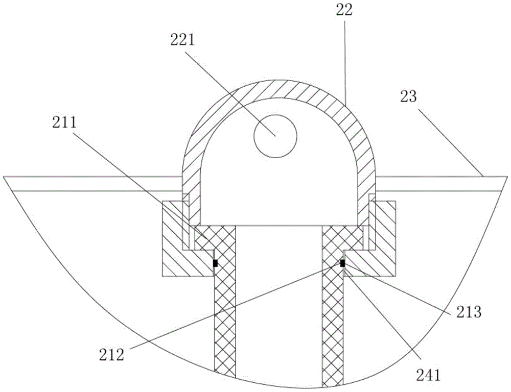
[0015] Examples, see e.g. Figures 1 to 2 Shown, a fiber cage for a loose fiber dyeing machine, comprising a frame 28, the top of the frame 28 has a connecting sleeve 22, the outer side wall of the connecting sleeve 22 is fixed with a plurality of support rods 23, the other end of the support rod 23 It is welded and fixed on the inner wall of the frame body 28, the bottom end of the connecting sleeve 22 is screwed with a fixed sleeve 24, the middle vertical pipe body 21 is inserted in the fixed sleeve 24, and the lower end of the middle vertical pipe body 21 is fixed with a lower connection. Cover 25, the lower connection sleeve 25 is screwed on the raised cover 26 that the bottom plate middle part o...


PUM


Abstract

The invention discloses a fiber cage for a loose fiber dyeing machine. The fiber cage comprises a frame body, wherein a connecting sleeve is arranged on the top of the frame body; a plurality of supporting rods are fixed on the outer side wall of the connecting sleeve; the other ends of the supporting rods are welded and fixed on the inner side wall of the frame body; a fixed sleeve is in threaded connection with the bottom end of the connecting sleeve; a middle vertical tube body is inserted in the fixed sleeve in a sleeving mode; a lower connecting sleeve is fixed at the lower end of the middle vertical tube body; the lower connecting sleeve is in threaded connection with a bulged sleeve which is arranged on the middle part of the bottom plate of the frame body; the middle vertical tube body is a net-shaped tube body; the lower end of the bulged sleeve is communicated with a bottom plate through hole in the center of the bottom plate of the frame body; a buffer fixed pad is fixed on the bottom surface of the bottom plate of the frame body; a felt pad layer is fixed on the bottom surface of the buffer fixed pad. The fiber cage is provided with a buffer mechanism, so that direct collision is reduced when the fiber cage is lifted into a dyeing cylinder, and the service life of the fiber cage is prolonged; meanwhile, the middle vertical tube body of the fiber cage can be replaced for conveniently maintaining and repairing the fiber cage without the needs of replacing the whole fiber cage.

Description

Technical field: [0001] The invention relates to the technical field of textile printing and dyeing equipment, in particular to a fiber cage for a loose fiber dyeing machine. Background technique: [0002] In the existing loose fiber dyeing machine, the fiber cage is hoisted into the dye vat, and there is no buffer device at the bottom of the dye vat, so that when the fiber cage is placed into the dye vat, it will collide with the dye vat, causing the dye vat to be damaged. At the same time, the existing There is a cylinder inside the fiber cage to ensure that the nozzle can be inserted into the cylinder for spraying, and the fiber material will not block the middle of the fiber cage. The cylinder is easy to be squeezed and damaged. After damage, the fiber needs to be removed Cage replacement, fiber cage replacement costs are high. Invention content: [0003] The purpose of the present invention is to overcome the deficiencies in the prior art, and provide a fiber cage fo...

Claims


Application Information

Patent Timeline
Patent Type & Authority Patents(China)
IPC IPC(8): D06B23/04
CPCD06B23/04
Inventor 陈永林
Owner 吴江市佳福纺织有限公司
Why Eureka
Try Eureka