

A loose fiber dyeing device with a rotatable fiber cage
A dyeing device and fiber cage technology, applied in the direction of processing textile material equipment configuration, textile material contact outlet textile material processing, etc., can solve the problems of affecting the recycling of dyes, damage to fiber cages and dye vats, and increasing maintenance costs. Not easy to agglomerate, reduce equipment maintenance costs, and reduce wear and tear
- Summary
- Abstract
- Description
- Claims
- Application Information
AI Technical Summary
Problems solved by technology
Method used
Image

Examples
Embodiment Construction
[0024] The specific implementation manners of the present invention will be further described in detail below in conjunction with the accompanying drawings and embodiments. The following examples are used to illustrate the present invention, but are not intended to limit the scope of the present invention.
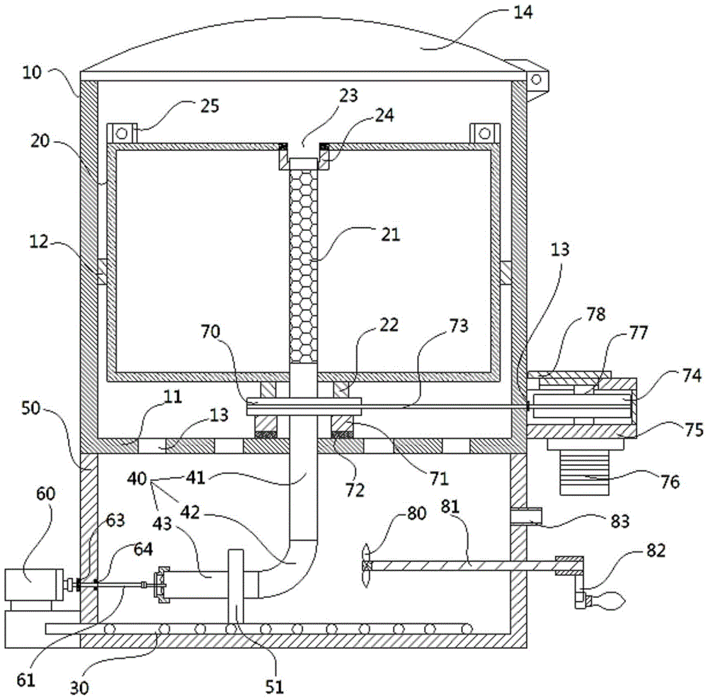
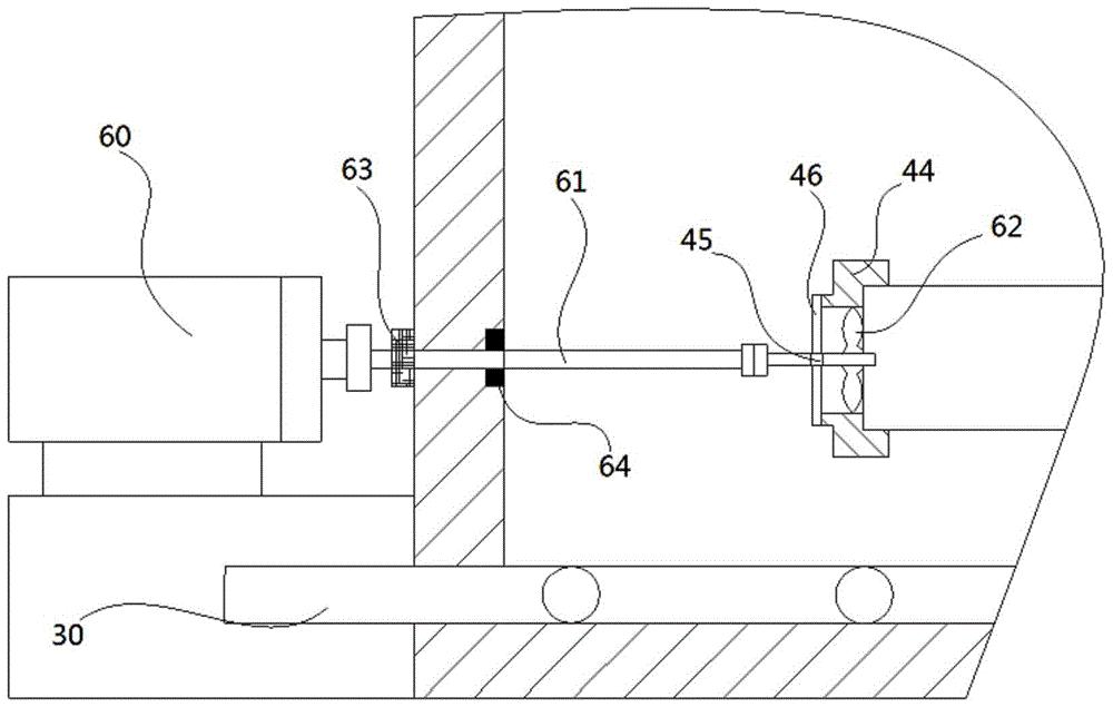
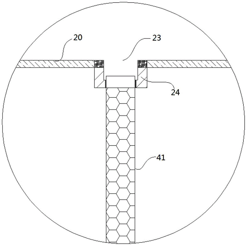
[0025] see Figure 1 to Figure 4 , the loose fiber dyeing device with rotatable fiber cage of the present invention comprises dyeing vat 10, fiber cage 20, heating coil 30 and center spray pipe 40, the bottom of described dyeing vat 40 is fixed with dye tank 50, and the dyestuff A heating coil 30 is fixed on the bottom of the tank 50, and one end of the heating coil 30 extends out of the dye tank 50 and communicates with the steam source; the outer wall of the dye tank 50 is fixed with a driving motor 60, and the output shaft of the driving motor 60 is passed through a shaft coupling. The device is connected with an intermediate rotating shaft 61, the intermediate rotatin...
PUM
 Abstract
Description
Claims
Application Information