Rotary dyeing device for loose fiber dyeing machine

A dyeing device and dyeing machine technology, applied in the direction of textile material contact export textile material processing, textile material carrier processing, textile material container processing, etc., can solve the problem of limited effect, easy extrusion damage of the cylinder, damage to the dyeing vat, etc. problems, to achieve the effect of convenient maintenance and repair, reduce direct collision and improve service life

Inactive Publication Date: 2016-08-10
吴江市永达丝绸整理有限责任公司
View PDF4 Cites 0 Cited by
  • Summary
  • Abstract
  • Description
  • Claims
  • Application Information

AI Technical Summary

Problems solved by technology

[0002] In the existing loose fiber dyeing machine, the fiber cage is hoisted into the dyeing vat, and there is no buffer device at the bottom of the dyeing vat, so that when the fiber cage is placed into the dyeing vat, it will collide with the dyeing vat, causing the dyeing vat to be damaged. At the same time, the existing There is a cylinder inside the fiber cage to ensure that the nozzle can be inserted into the cylinder for spraying, and the fiber material will not block the middle of the fiber cage. The cylinder is easy to be squeezed and damaged. After damage, the fiber needs to be removed Cage replacement, high cost of fiber cage replacement
[0003] Moreover, the existing fiber cage generally does not move after being placed in the dye vat, so that when the spray pipe sprays liquid, the loose fibers in the fiber cage cannot be sprayed evenly, but can only be sprayed gradually by the dyestuff. Dip dyeing, limited effect

Method used


Image

  • Rotary dyeing device for loose fiber dyeing machine
  • Rotary dyeing device for loose fiber dyeing machine

Examples


Embodiment Construction

[0017] The present invention will be described in detail below in conjunction with accompanying drawings and specific preferred embodiments, so that the advantages and features of the present invention can be more easily understood by those skilled in the art. range is limited.

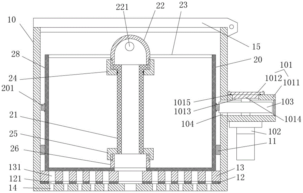
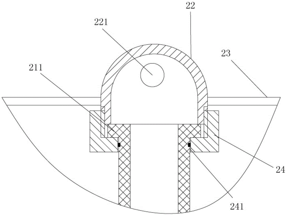
[0018] Examples, see e.g. Figures 1 to 2 Shown is a rotary dyeing device for a loose fiber dyeing machine, comprising a dyeing vat 10 and a fiber cage 20, the fiber cage 20 is placed in the dyeing vat 10, the inside wall of the dyeing vat 10 has a limit ring 11, and the outer wall of the fiber cage 20 Close to the inner side wall of the limit ring 11, a buffer pad 12 is fixed on the bottom plate of the dyeing vat 10, and a wear-resistant lubricating block 13 is fixed on the buffer pad 12. The bottom of the fiber cage 20 is pressed against the wear-resistant lubricating block 13, and the fiber The outer wall of the cage 20 is fixed with a rotating ring gear 201, the outer wall of the dye vat 10 has a...


PUM


Abstract

The invention discloses a rotary type dyeing device for a loose fiber dyeing machine. The rotary type dyeing device comprises a dyeing cylinder and a fiber cage, wherein the fiber cage is placed in the dyeing cylinder; a limiting ring is arranged on the inner side wall of the dyeing cylinder; the outer wall of the fiber cage is tightly clung to the inner side wall of the limiting ring; a buffer pad is fixed on the bottom plate of the dyeing cylinder; a wear-resisting lubricating block is fixed on the buffer pad; the bottom of the fiber cage is pressed against the wear-resisting lubricating block; a rotary gear ring is fixed on the outer wall of the fiber cage; a gear housing is arranged on the outer wall of the dyeing cylinder; a rotary motor is fixed on the bottom of the gear housing; an output shaft of the rotary motor extends into the gear housing; a drive gear is fixed on the output shaft of the rotary motor; the drive gear partially penetrates through a connecting through slot in the side wall of the dyeing cylinder and extends into the dyeing cylinder; the drive gear is engaged with the rotary gear ring. The rotary type dyeing device is provided with a buffer mechanism, so that the direct collision is reduced when the fiber cage is lifted into a dyeing cylinder, and the service life of the fiber cage is prolonged; meanwhile, the fiber cage can be rotated, so that the sprayed dyes are enabled to be uniform.

Description

Technical field: [0001] The invention relates to the technical field of textile printing and dyeing equipment, in particular to a rotary dyeing device for a loose fiber dyeing machine. Background technique: [0002] In the existing loose fiber dyeing machine, the fiber cage is hoisted into the dye vat, and there is no buffer device at the bottom of the dye vat, so that when the fiber cage is placed into the dye vat, it will collide with the dye vat, causing the dye vat to be damaged. At the same time, the existing There is a cylinder inside the fiber cage to ensure that the nozzle can be inserted into the cylinder for spraying, and the fiber material will not block the middle of the fiber cage. The cylinder is easy to be squeezed and damaged. After damage, the fiber needs to be removed Cage replacement, fiber cage replacement costs are high. [0003] Moreover, the existing fiber cage generally does not move after being placed in the dye vat, so that when the spray pipe spra...

Claims


Application Information

Patent Timeline
Patent Type & Authority Patents(China)
IPC IPC(8): D06B23/04D06B23/14D06B1/08
Inventor 陈永林
Owner 吴江市永达丝绸整理有限责任公司
Why Eureka
Try Eureka