Rail type multi-leaf door with automatic door locking, unlocking, opening and closing functions

A technology for automatic opening and closing and door functions, which is applied in the layout of wings, building fastening devices, buildings, etc., can solve the problems of low safety factor, short life of accessories, low safety, etc., to achieve easy control and operation, taking into account Good aesthetics and anti-theft performance

Inactive Publication Date: 2015-06-03
GUANGXI PINGGUO LVANFU DOOR IND CO LTD
6 Cites 0 Cited by

AI-Extracted Technical Summary

Problems solved by technology

[0002] At present, garage doors, entrance doors and warehouse doors are mainly rolling gates. Rolling gates mainly have relatively high requirements for motors, short life of accessories, high noise, size is limited by the size of the curtain, poor anti-theft performance, and high cost. High-level disadvantages...

Abstract

The invention discloses a rail type multi-leaf door with automatic door locking, unlocking, opening and closing functions. The rail type multi-leaf door comprises a door frame, a corner rail, a plurality of narrow doors and a wide door, wherein the plurality of narrow doors are connected through hinges, the wide door is matched with the last narrow door, the plurality of narrow doors slide along the corner rail, a locking mechanism is installed on the last narrow door, an unlocking rod which can press the locking mechanism downward is installed on the wide door, a chain of which the walking direction is the same as that of the corner rail is arranged above the corner rail, and two pull rods which are respectively connected with the first narrow door and the last narrow door are installed on the chain. Compared with existing roller shutter type and sliding type doors, the rail type multi-leaf door with the automatic door locking, unlocking, opening and closing functions has the advantages of simultaneous realization in door closing and locking, simplicity and convenience in control operation, low price and good anti-theft performance and can be used for folding a multi-leaf door. The door can be made of wood, metal, glass and the like, and additionally, attractive appearance, practicability and safety are considered.

Application Domain

Construction fastening devicesWing arrangements

Technology Topic

Anti theftEngineering +2

Image

  • Rail type multi-leaf door with automatic door locking, unlocking, opening and closing functions
  • Rail type multi-leaf door with automatic door locking, unlocking, opening and closing functions
  • Rail type multi-leaf door with automatic door locking, unlocking, opening and closing functions

Examples

  • Experimental program(1)

Example Embodiment

[0015] The structure of the present invention will be further explained below in conjunction with the drawings:
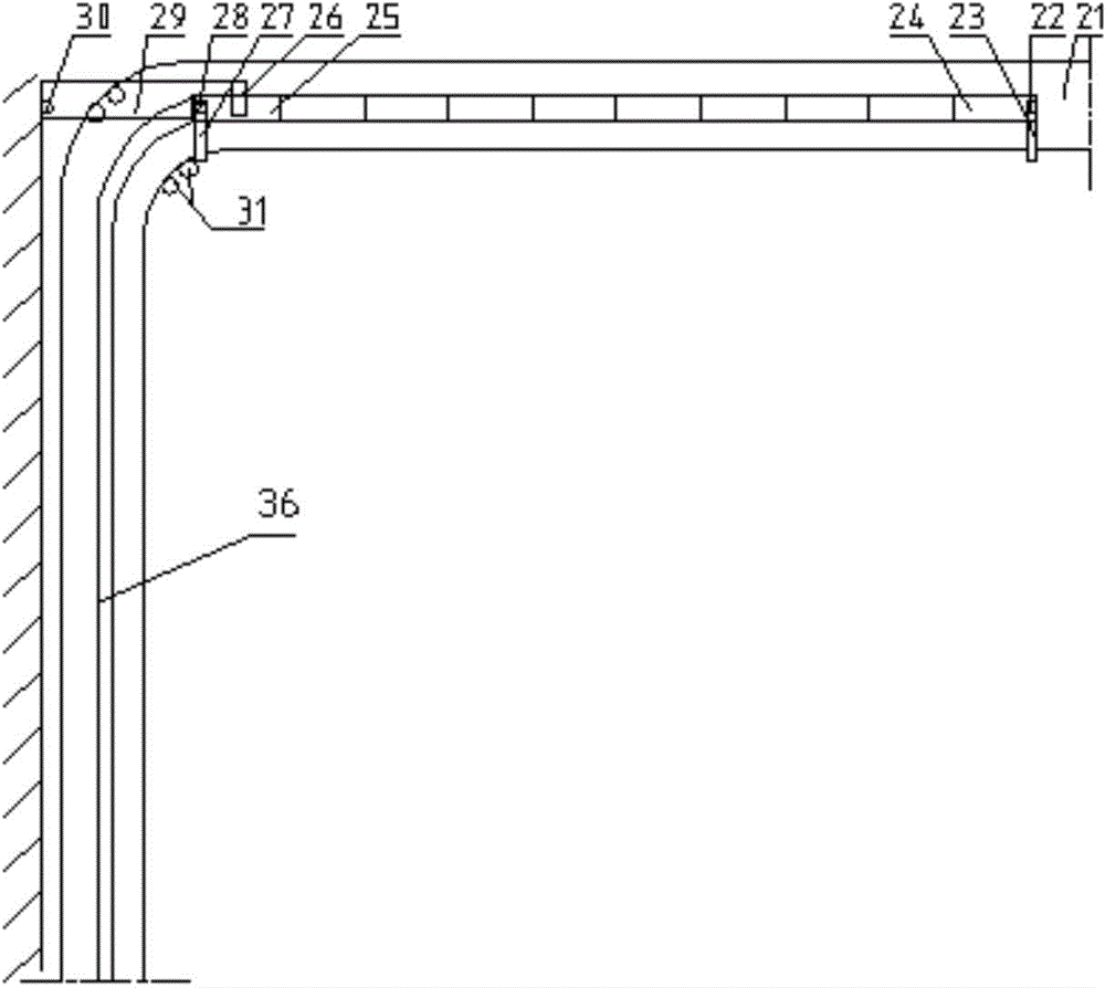
[0016] Such as figure 1 As shown, the chain 21 is installed on the door frame, and all narrow doors are connected by hinges 34. The side of the last narrow door 25 is provided with a wide door 29 connected to the door frame by a shaft 30, and the wide door 29 is next to the end. The narrow door 25, the first narrow door 24 is fixed with a first fixed shaft 22 on the upper right end surface, the last narrow door 25 is fixed with a second fixed shaft 28, the first fixed shaft 22 and the second fixed shaft 28 They are respectively connected to the first pull rod 23 and the second pull rod 27. The other ends of the first pull rod 23 and the second pull rod 27 are fixed on the chain 21; all narrow doors slide along the corner rail 36, and the chain 21 is set above the corner rail 36, The walking direction is the same as the corner track 36. The chain 21 is equipped with a support column 31 at the inner side of the turn; a locking mechanism is installed on the last narrow door 25, and an unlocking lever 26 that can press the locking mechanism down is installed on the wide door 29 , The movement of the chain 21 and the opening of the wide door 29 can be driven by a movable source.
[0017] The locking mechanism used in the present invention is such as figure 2 As shown, it includes a first shaft 2 and a second shaft 9 installed on the final door body 25 and arranged in parallel in the vertical direction. The upper and lower ends of the first shaft 2 can extend outside the door body 1, and the upper end is The unlocking lever 26 controls the first shaft 2 to move down, and its lower end can be inserted into the lock hole at the bottom of the door frame. A first fixing plate 8 that can clamp the extension channel is fixed on the upper part of the first shaft 2, and the first shaft 2 is installed There is a first spring 4, one end of the first spring 4 is connected to the first fixed plate 8, and the other end is connected to the first connecting bridge 3 provided on the door body, and the first shaft 2 passes through the hole on the first connecting bridge 3 , The hole diameter of the first connecting bridge 3 is larger than the diameter of the first shaft 2 and smaller than the diameter of the first spring 4; the top of the second shaft 9 can extend out of the door body and be inserted into the lock hole on the top of the door frame, and the lower part of the second shaft 9 is fixed There is a second fixed disk 13, the second spring 11 is mounted on the second shaft 9, one end of the second spring 11 is blocked by the second connecting bridge 10 provided on the door body, and the other end is connected to the second fixed disk 13. A fixed pulley 7 installed in the door body is arranged between the first shaft 2 and the second shaft 2. The connecting rope 6 is wound on the fixed pulley 7, one end of which is connected to the first fixed rod 5, and the other end is connected to the second fixed rod 12. The other end of the first fixed rod 5 is fixedly connected to the first shaft 2, and the other end of the second fixed rod 12 is fixedly connected to the second fixed plate 13 on the second shaft 9.
[0018] In order to further make the narrow door run stably at the corner, the top of each narrow door is provided with a fixed shaft, and the connecting rod is connected between the fixed shafts, such image 3 As shown, the tops of the two narrow doors are respectively fixed with a fourth fixed shaft 35 and a third fixed shaft 32, and a connecting rod 33 is connected between the fourth fixed shaft 35 and the third fixed shaft 32 in a hinged manner.
[0019] The end of the unlocking lever 26 fixedly connected to the wide door 29 is wedge-shaped, such as Figure 4 As shown, the wedge-shaped end makes it easy to move the unlocking lever 26 into and out of the top of the first shaft 2 of the locking mechanism to achieve locking and unlocking actions.
[0020] The transmission principle of the present invention is as follows:
[0021] 1. The locking process of the locking mechanism: When pressure is applied to the upper end of the first shaft 2 by the end of the unlocking lever 26, the first shaft 2 moves down with the first fixed plate 8 and then moves the first spring 4 Compression; when the first shaft 2 moves down, the first fixed rod 5 is driven to move downward, the first fixed rod 5 pulls the connecting rope 6 connected to it, and the connecting rope 6 drives the second fixed rod around the fixed pulley 7 12 moves upward, the second fixed rod 12 drives the second fixed plate to move upward, and then drives the second shaft 9 to move upward, and the second spring 11 is compressed; when the upper part of the first shaft 2 is completely pressed into the door, the first shaft The lower end of the second shaft 9 enters the lock hole at the lower part of the door frame, and the upper end of the second shaft 9 enters the lock hole at the upper part of the door frame. At this time, the narrow end door 25 is locked up and down simultaneously.
[0022] 2. The unlocking process of the locking mechanism: When the unlocking lever 26 is separated from the upper end of the first shaft 2, under the elastic force of the first spring 4 and the second spring 11, the locking mechanism realizes the movement opposite to the locking process, and finally One shaft 2 moves upwards, the upper end returns to the position shown in the figure, and the lower end escapes from the lock hole at the lower part of the door frame; the second shaft 11 moves downward, and the upper end escapes from the lock hole at the upper part of the door frame.
[0023] 3. The movement of the wide door 29 and the narrow door can be controlled by two dynamic sources. When the narrow door is closed, the wide door 29 can block the narrow door from moving to the left and close tightly.
[0024] 4. The support column 31 installed on the inner side of the turn of the chain 21 is to support the chain 21.
[0025] 5. The narrow door is designed to allow the door to pass smoothly at the turn of the chain 21.
[0026] 6. The movement process of the door from closing to opening: First, the control source of the wide door 29 is activated to open the wide door 29 to the outside, and the wide door 29 drives the unlocking lever 26 to move outside the first axis 2 during the rotation. The first shaft 2 pops out, and the locking mechanism is unlocked (you can add a locking mechanism to other doors as needed); when the wide door 29 is opened and the narrow door is unlocked, the rotating device is activated to drive the chain 21 to move to the left, and the chain 21 drives and fixes it. The first pull rod 23 and the second pull rod 27 move along the chain 21, the first pull rod 23 and the second pull rod 27 drive the first fixed shaft 22 and the second fixed shaft 28 connected to it to move along the chain 21, thereby driving All narrow doors move along the chain 21. When the last narrow door 25 reaches the bottom end of the other side of the chain 21, the rotation of the chain 21 is stopped and the door is fully opened.
[0027] 7. The movement process of the door from opening to closing: The movement process of the door from closing to opening is completely opposite. The locking mechanism of the locking mechanism is to press down the first shaft 2 by the wedge-shaped end of the lower part of the unlocking lever 26.
[0028] 8. The power source and chain 21 can also be replaced by a self-propelled trolley.
[0029] 9. This mechanism can be applied to any number of doors. The number of narrow doors here is only a schematic diagram. The number of narrow doors and locking mechanisms can be installed according to actual needs.

PUM

no PUM

Description & Claims & Application Information

We can also present the details of the Description, Claims and Application information to help users get a comprehensive understanding of the technical details of the patent, such as background art, summary of invention, brief description of drawings, description of embodiments, and other original content. On the other hand, users can also determine the specific scope of protection of the technology through the list of claims; as well as understand the changes in the life cycle of the technology with the presentation of the patent timeline. Login to view more.

Similar technology patents

Offset support cantilever type piezoelectric inertia impact precision driver

InactiveCN101068100ASimplify drive signal generation systemeasy to control
Owner:JILIN UNIV

Blue-purple light or blue light excitation fluorophor, preparation method thereof, and packaged white light diode

InactiveCN101186818AProcess environmental protectioneasy to control
Owner:TIANJIN UNIVERSITY OF TECHNOLOGY

Classification and recommendation of technical efficacy words

  • Easy to control
  • low price
Why Eureka
Try Eureka