Valve element structure with high pressure difference and low flow

A technology of flow valve and high pressure difference, which is applied in the direction of lifting valve, valve device, engine components, etc., to achieve the effect of increasing life, easy high-precision adjustment, and enhancing the ability to reduce pressure

Inactive Publication Date: 2015-06-03
WUXI SMART AUTO CONTROL ENG CO LTD
View PDF6 Cites 4 Cited by
  • Summary
  • Abstract
  • Description
  • Claims
  • Application Information

AI Technical Summary

Problems solved by technology

In general, valve manufacturers adopt the method of increasing the hardness of valve trim materials to resist the erosion of the medium, which can only prolong the service life of the valve trim, but cannot fundamentally solve the problem of flashing or cavitation of the medium

Method used


Image

  • Valve element structure with high pressure difference and low flow
  • Valve element structure with high pressure difference and low flow
  • Valve element structure with high pressure difference and low flow

Examples


Embodiment Construction

[0015] The present invention will be further described below in conjunction with specific drawings.

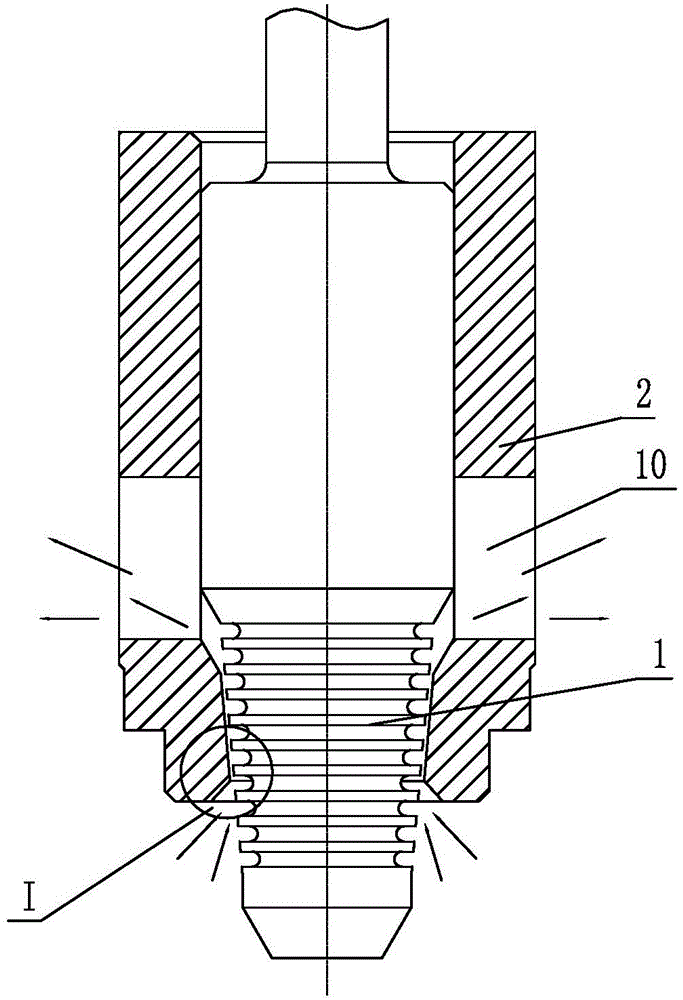
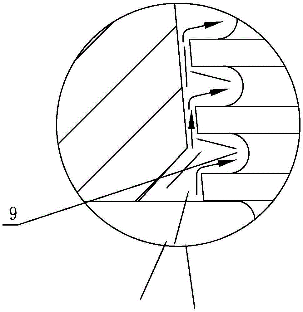
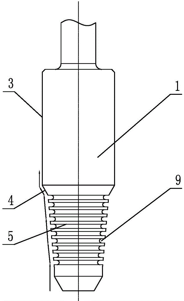
[0016] Such as Figure 1 ~ Figure 4 As shown: the valve core structure with high pressure difference and small flow includes valve core 1, valve seat 2, valve core guide surface 3, valve core sealing surface 4, valve core cone surface 5, valve seat guide surface 6, valve seat sealing surface 7 , Valve seat cone 8, groove 9, adjustment window 10, etc.

[0017] Such as figure 1 As shown, the present invention includes a valve seat 2 and a valve core 1 arranged in the inner cavity of the valve seat 2. The valve core 1 is sequentially divided into a valve core guide surface 3, a valve core sealing surface 4 and a valve core cone surface 5 from top to bottom. Three sections, a plurality of grooves 9 parallel to each other are opened on the conical surface 5 of the valve core, and the depth of each groove 9 is equal; 1. Valve seat sealing surface 7 and valve seat cone surface 8 t...


PUM


Abstract

The invention relates to a valve element structure with high pressure difference and low flow. The valve element structure comprises a valve seat and a valve element which is arranged in an inner cavity of the valve seat. The valve element structure is characterized in that the valve element is successively divided into three sections, namely a valve element guide surface, a valve element sealing surface and a valve element conical surface from upside to downside. Multiple parallel slots are formed in the valve element sealing surface; the inner cavity of the valve seat is successively divided into three sections, namely a valve seat guide surface, a valve seat sealing surface and a valve seat conical surface from upside to downside. An adjustment window is formed on the valve seat guide surface; the valve element guide surface, the valve element sealing surface and the valve element conical surface are respectively matched with the valve seat guide surface, the valve seat sealing surface and the valve seat conical surface. The valve element structure with high pressure difference and low flow is simple in structure and good in economical efficiency, and prevents gas erosion.

Description

technical field [0001] The invention relates to a valve core structure, in particular to a valve core structure with high pressure difference and small flow rate, belonging to the technical field of fluid control valves. Background technique [0002] At present, in chemical industry, electric power, metallurgy and other industries, there are often harsh working conditions with high pressure difference and small flow. When the regulating valve as a fluid control terminal component is faced with flashing or cavitation that may occur in the liquid medium during use, the valve trim will be quickly damaged, the valve adjustment function will be lost, and the service life of the product will be greatly reduced. In general, valve manufacturers adopt the method of increasing the hardness of valve trim material to resist the erosion of the medium. This can only prolong the service life of the valve trim, but cannot fundamentally solve the problem of flashing or cavitation of the medi...

Claims


Application Information

Patent Timeline
Patent Type & Authority Applications(China)
IPC IPC(8): F16K1/36
CPCF16K1/38
Inventor 陈彦徐刚王汪洋王文明
Owner WUXI SMART AUTO CONTROL ENG CO LTD
Why Eureka
Try Eureka