Inner reflection lamp

一种内反射、灯具的技术,应用在照明领域,能够解决缩减灯源使用寿命、产生高热等问题,达到灯具体积容易、效率高、出光角度容易控制的效果

Inactive Publication Date: 2015-06-03
周焕球
View PDF12 Cites 17 Cited by
  • Summary
  • Abstract
  • Description
  • Claims
  • Application Information

AI Technical Summary

Problems solved by technology

However, high-power light-emitting diodes have the disadvantage of generating high heat, which is the main reason for reducing the service life of light sources

Method used


Image

  • Inner reflection lamp
  • Inner reflection lamp
  • Inner reflection lamp

Examples


Embodiment Construction

[0031] The internal reflection lamp of the present invention will be further described in detail below in conjunction with specific embodiments and accompanying drawings.

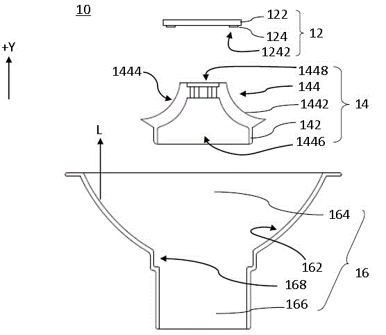
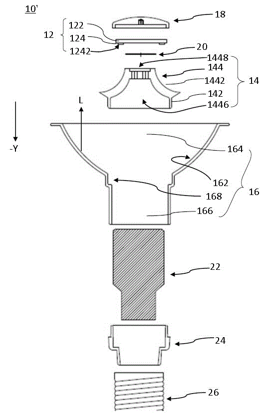
[0032] Please refer to figure 1 , is an exploded schematic view of the internal reflection lamp according to Embodiment 1 of the present invention, wherein all components are cut along the optical axis. Such as figure 1 As shown, the internal reflection lamp 10 includes a light emitting unit 12 , a reflector 14 and a cup 16 . exist figure 1 In the description, the internal reflection lamp 10 is described by taking PAR30 as an example.

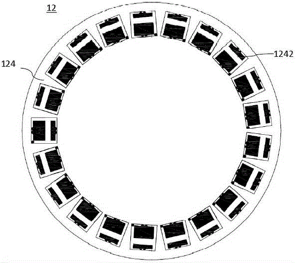
[0033] The light emitting unit 12 includes a circular plate-shaped light bottom 122 and a light emitting portion 124 fixed on the light bottom 122 . Specifically, the light-emitting part 124 is fixed on the side of the lamp bottom 122 facing the reflector 14, so that the light emitted by the light-emitting part 124 will not be directly emitted to the outside of the lamp,...


PUM


Abstract

The invention relates to an inner reflection lamp. The inner reflection lamp includes a light emitting unit, a reflector, and a cup body accommodating the light emitting unit and the reflector. The light emitting unit and the reflector are fixedly connected on the cup body to form a reflection curved surface having a first reflective layer. The cup body is equipped with a second reflective layer, a first accommodation space and a fixing groove. The second reflective layer is formed on the inner wall of the cup body. The fixing groove is used for accommodating the reflector so that the first reflective layer is exposed in the first accommodation space. Rays emitted from the light emitting unit are reflected to the second reflective layer through the first reflective layer and then are emitted from the cup body. A whole body of the inner reflection lamp serves as a heat dissipation element of the lamp, a special-purpose heat dissipation structure is not needed, the heat dissipation area is large, the efficiency is high, and the lamp can be butt joint to conventional lamps in a seamless manner. Rays emitted from the light emitting unit are all emitted from the lamp after refraction. The light emitting angle is easy to control. The light emitting unit is prevented from being seen by a user from the outside of the inner reflection lamp.

Description

technical field [0001] The invention relates to the technical field of lighting, in particular to an internal reflection lamp with high heat dissipation efficiency and uniform light output. Background technique [0002] In traditional lamps, a light source is arranged at the center of the lamp. Although this arrangement can directly output the light generated by the light emitting source, it is difficult for the lamp to adjust the light emitting angle and light distribution of the light emitting source. Furthermore, the user will directly see the light source, thereby affecting the aesthetics of the lamp. [0003] Therefore, a lamp with a radiator is produced. The light source of the lamp is fixed under the radiator to prevent users from viewing the light source directly; However, due to the limited conduction capacity and conduction distance of this structure, the light source has a serious problem of light attenuation. [0004] With people's demand for energy saving and...

Claims


Application Information

Patent Timeline
Patent Type & Authority Applications(China)
IPC IPC(8): F21S2/00F21V7/00F21V29/503F21V29/70F21V17/16
CPCF21V7/0008F21V7/0033F21K9/23F21Y2103/33F21Y2115/10F21V23/006F21K9/238F21V29/15F21V29/70F21V7/0091F21V29/75
Inventor 周焕球
Owner 周焕球
Why Eureka
Try Eureka