Frequency response characteristic calibration method, device and system of waveform generator
A waveform generator and frequency response characteristics technology, applied in the field of waveform generator frequency response characteristics calibration, can solve the problems of amplitude oscillation attenuation, low-pass, uneven frequency response characteristics, etc., to achieve the effect of improving calibration accuracy and flatness
- Summary
- Abstract
- Description
- Claims
- Application Information
AI Technical Summary
Problems solved by technology
Method used
Image

Examples
Embodiment Construction
[0019] The present invention will be further described in detail below through specific embodiments in conjunction with the accompanying drawings.
[0020] The method, device and system of the present application are suitable for waveform generators. In the embodiments of this application, arbitrary waveform generators are used as examples for illustration. In other embodiments, they are also applicable to other specific waveform generators, such as sine waves and sawtooth waves. generator etc.
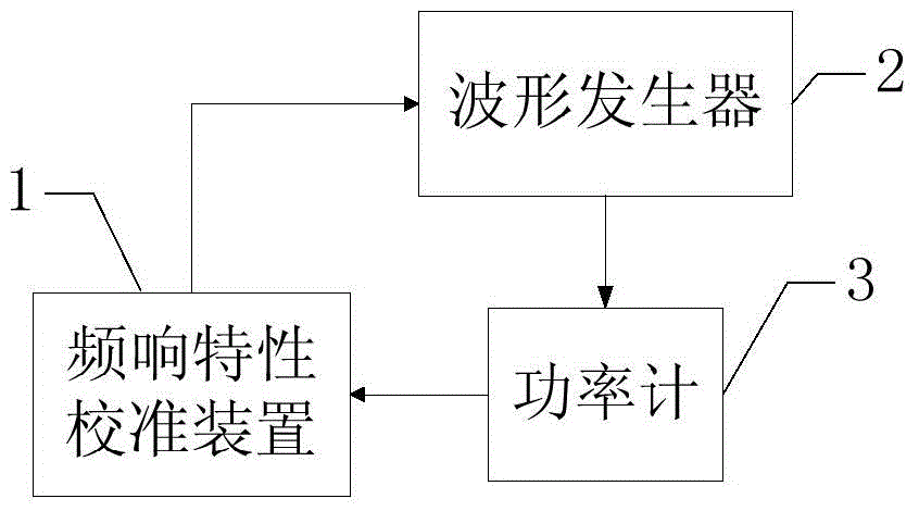
[0021] Please refer to figure 2 , which is a structural schematic diagram of a waveform generator frequency response characteristic calibration system disclosed in this embodiment, the system includes: a power meter 3 and a frequency response characteristic calibration device 1, wherein the power meter 3 is used to communicate with the waveform generator 2 to be calibrated Connect, the power meter 3 detects the frequency point f specified by the waveform generator 2 to be calibrated...
PUM
 Abstract
Description
Claims
Application Information
 - R&D
- Intellectual Property
- Life Sciences
- Materials
- Tech Scout
- Unparalleled Data Quality
- Higher Quality Content
- 60% Fewer Hallucinations
Browse by: Latest US Patents, China's latest patents, Technical Efficacy Thesaurus, Application Domain, Technology Topic, Popular Technical Reports.
© 2025 PatSnap. All rights reserved.Legal|Privacy policy|Modern Slavery Act Transparency Statement|Sitemap|About US| Contact US: help@patsnap.com