Rubber-frame-free LCD display device

A display device and borderless technology, which is applied in nonlinear optics, instruments, optics, etc., can solve the problem of limiting borderless

Inactive Publication Date: 2015-06-03
WUXI BOYI PHOTOELECTRIC TECH
View PDF0 Cites 1 Cited by
  • Summary
  • Abstract
  • Description
  • Claims
  • Application Information

AI Technical Summary

Problems solved by technology

As the current LCD display device is developing in the direction of no frame, the traditional large-size backlight limits the effect of narrower frame brought by no frame

Method used


Image

  • Rubber-frame-free LCD display device
  • Rubber-frame-free LCD display device

Examples


Embodiment Construction

[0011] The specific embodiments of the present invention will be further described below in conjunction with the accompanying drawings.

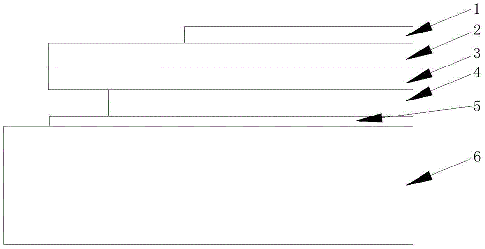
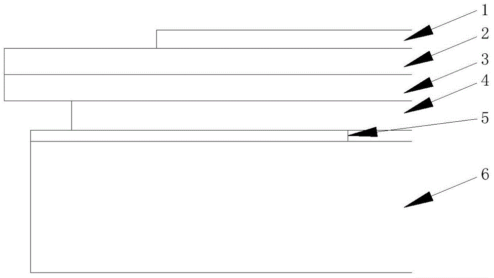
[0012] Such as figure 2 As shown, the present invention includes an LCD screen formed by stacking an upper glass 2 and a lower glass 3, an upper polarizer 1 is stacked above the upper glass 2, a lower polarizer 4 is stacked below the lower glass 3, and the lower polarizer 4 passes through both sides. The glue 5 is connected with the backlight source 6, and the size of the backlight source 6 is smaller than the size of the LCD screen.

[0013] What is described above is only a preferred embodiment of the present invention, and the present invention is not limited to the above examples. It can be understood that other improvements and changes directly derived or conceived by those skilled in the art without departing from the basic idea of ​​the present invention shall be considered to be included in the protection scope of the present inven...


PUM


Abstract

The invention discloses a rubber-frame-free LCD display device. The rubber-frame-free LCD display device comprises an LCD screen formed by stacking upper glass and lower glass. An upper polarizer is stacked on the upper glass, a lower polarizer is stacked under the lower glass, the lower polarizer is bonded with a backlight source through a two-sided adhesive, and the backlight source is smaller than the LCD screen in size. The backlight source is smaller than the LCD screen in size through design, so that the size of the LCD screen is appearance size of the whole LCD display device, and real fame omission is achieved.

Description

technical field [0001] The invention relates to the technical field of liquid crystal display, in particular to a frameless LCD display device. Background technique [0002] The structure of a conventional LCD display device is as follows figure 1 As shown, it includes an LCD screen formed by stacking upper glass 2 and lower glass 3. The upper and lower sides of the LCD screen are respectively stacked with an upper polarizer 1 and a lower polarizer 4. The backlight 6 is glued to the lower polarizer 4 through double-sided adhesive 5 connected, and the size of the backlight source 6 is larger than that of the LCD screen. Since the current LCD display device is developing towards a frameless direction, the traditional large-size backlight source limits the effect of a narrower frame brought by the frameless. Contents of the invention [0003] The purpose of the present invention is to provide a frameless LCD display device to realize a real frameless design. [0004] Techn...

Claims


Application Information

Patent Timeline
IPC IPC(8): G02F1/13357
CPCG02F1/133608
Inventor 乔伟雄王建治黄海慧
Owner WUXI BOYI PHOTOELECTRIC TECH
Why Eureka
Try Eureka