

Magnetic Field Balanced Distributed Wireless Power Transfer System Based on Magnetic Resonance Coupling
A technology of wireless power transmission and magnetic resonance coupling, which is applied in the direction of electrical components and circuit devices, can solve the problems of non-conformity to humanized requirements, decreased transmission efficiency, and unbalanced magnetic field distribution, and achieves a small decrease in transmission efficiency and under-coupling The effect of alleviating and saving processing costs
- Summary
- Abstract
- Description
- Claims
- Application Information
AI Technical Summary
Problems solved by technology
Method used
Image

Examples
Embodiment 1
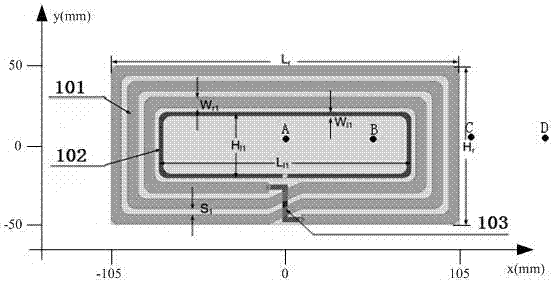
[0047] Example 1: Adopt figure 1 The transmitter shown and Figure 5 , Image 6 The receiving end shown is a rectangular ordinary flat panel wireless power transmission system that can be used in portable computers, tablet computers, LED lighting equipment and speakers.
[0048] The structure diagrams of the transmitting module and the receiving module are as follows: figure 1 with Figure 5 , Image 6 As shown in the back side, there is no metal sheet attached.
[0049] according to figure 1 with Figure 5 , Image 6 The symbol identification in the structural diagram shown in, combined with actual application requirements, the design in this embodiment adopts the following geometric parameters and electrical parameters:
[0050] Table 1 Geometric parameters and electrical parameters of the transmitting module and the receiving module in Example 1
[0051] Symbol mark Ranges) Lr
210(mm) Hr
100(mm) Wr1
6-7(mm) Wl1
2-4(mm) Hl1
20-26(mm)
[0052] Ll1
150-156(mm) S1
3-4(mm) Reson...
Embodiment 2
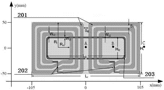
[0059] Example 2: Adopt figure 2 The transmitter shown and Picture 9 , Picture 10 The receiving end shown can be used in a magnetic field balance distribution type wireless power transmission system for portable computers, tablet computers, LED lighting equipment and speakers.
[0060] The structure diagrams of the transmitting module and the receiving module are as follows: figure 2 with Picture 9 , Picture 10 As shown in the back side, there is no metal sheet attached.
[0061] according to figure 2 with Picture 9 , Picture 10 The symbol identification in the structural diagram shown in, combined with actual application requirements, the design in this embodiment adopts the following geometric parameters and electrical parameters:
[0062] Table 2 Geometric parameters and electrical parameters of the transmitting module and the receiving module in Example 2
[0063] Symbol mark Ranges) Lr
210(mm) Hr
100(mm) Wr2
6.0-6.6(mm) Wl2
1-3(mm) Hl2
42-45(mm) Ll2
152-156(mm) Rl
50...
Embodiment 3
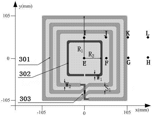
[0072] Example 3: Adopt image 3 The transmitter shown and Figure 5 , Image 6 The receiving end shown is a square ordinary flat panel wireless power transmission system that can be used in portable computers, tablet computers, LED lighting equipment and speakers.
[0073] The structure diagrams of the transmitting module and the receiving module are as follows: image 3 with Figure 5 , Image 6 As shown in the back side, there is no metal sheet attached.
[0074] according to image 3 with Figure 5 , Image 6 The symbol identification in the structural diagram shown in, combined with actual application requirements, the design in this embodiment adopts the following geometric parameters and electrical parameters:
[0075] Table 4 Geometric parameters and electrical parameters of the transmitting module and the receiving module in Embodiment 3
[0076] Symbol mark Ranges) R1
105(mm) R2
42-46(mm) W1
4-6(mm) W2
4-6(mm) Sl
8.5-10(mm) Transmitter resonant capacitance value (303) 5...
PUM
 Abstract
Description
Claims
Application Information