
Clutch body of a synchronisation device of a variable speed transmission of a motor vehicle and method for the production thereof

A technology of gear transmission and synchronous device, which is applied in the direction of mechanically driven clutches, clutches, mechanical equipment, etc., and can solve problems such as the realization of a stable process and the technical limit of the modification process.

Inactive Publication Date: 2015-06-03
SCHAEFFLER TECH AG & CO KG
View PDF4 Cites 0 Cited by
  • Summary
  • Abstract
  • Description
  • Claims
  • Application Information

AI Technical Summary

Problems solved by technology

[0005] As a result, the retrofit process reaches technological limits, so that a process-stable implementation is no longer feasible from a certain order of magnitude of the proposed diameter ratios

Method used


Image

  • Clutch body of a synchronisation device of a variable speed transmission of a motor vehicle and method for the production thereof
  • Clutch body of a synchronisation device of a variable speed transmission of a motor vehicle and method for the production thereof
  • Clutch body of a synchronisation device of a variable speed transmission of a motor vehicle and method for the production thereof

Examples


Embodiment Construction

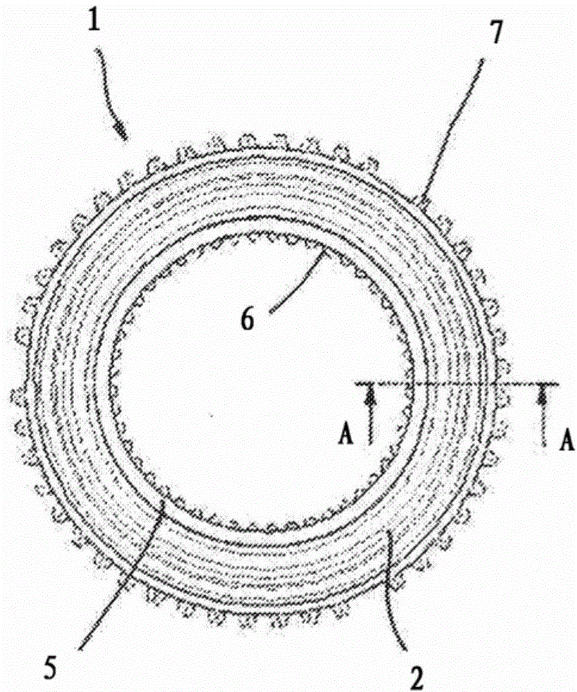
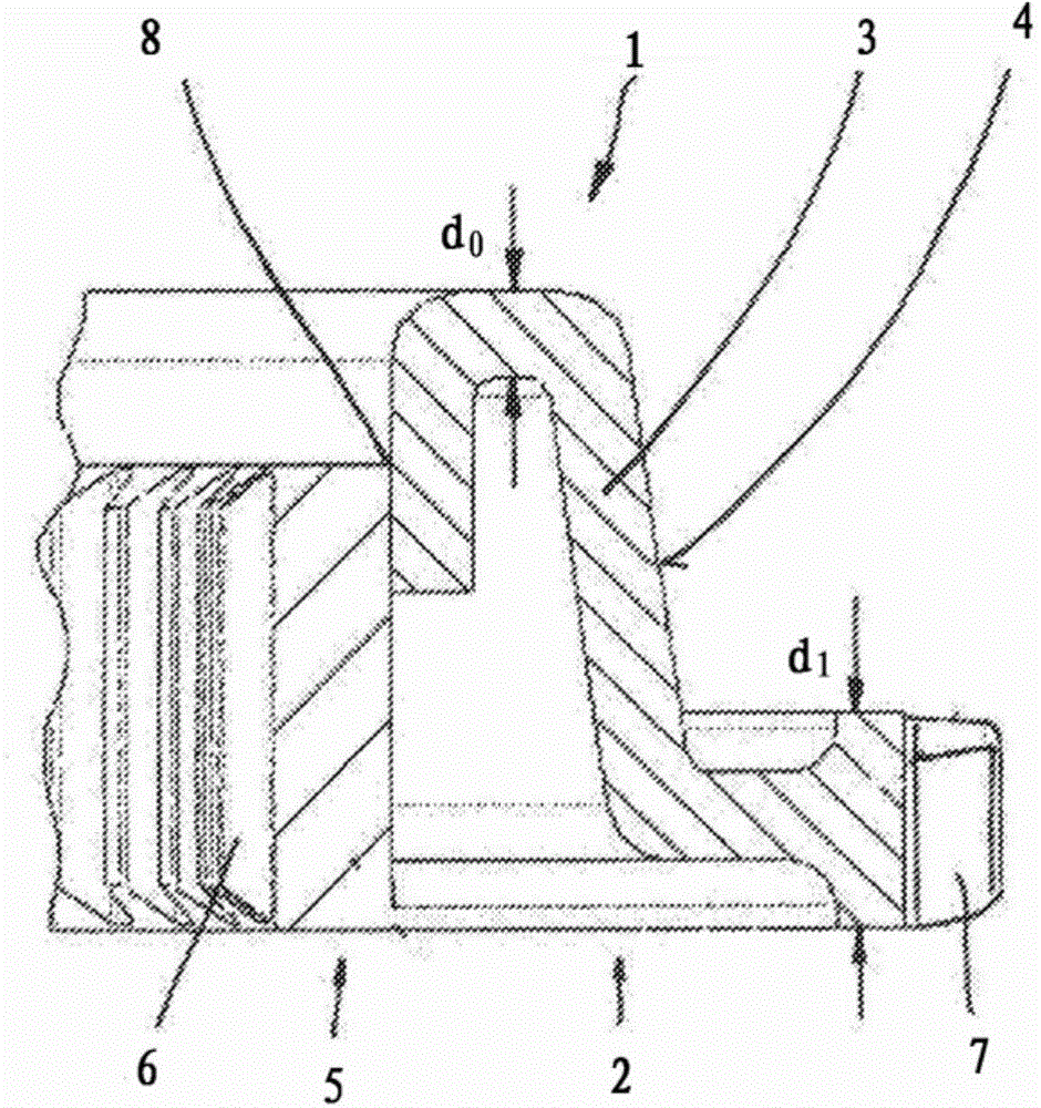
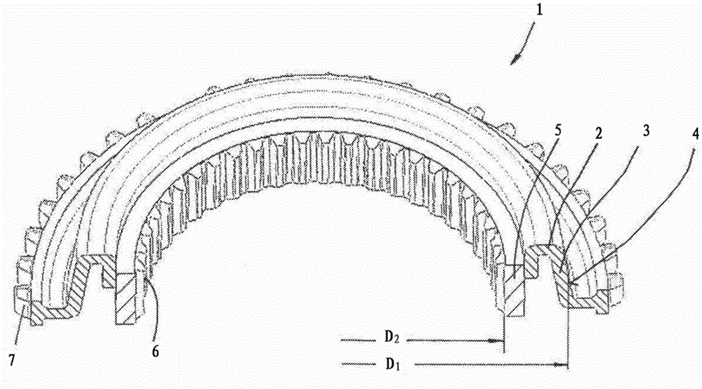
[0027] The figures show different views of a coupling body 1 which belongs to a synchronizing device of a motor vehicle gear transmission. The coupling body 1 is designed in two parts. It has a radially outer coupling disk section 2 and a radially inner carrier section (ie hub) 5 .

[0028] The coupling disc segment 2 is manufactured from a steel disc having an original thickness d 0 . Formed by stamping and bending or deep drawing as especially from figure 2 The shape obtained from . The coupling disk section 2 therefore has a friction cone 3 with a wedge-shaped friction cone surface 4 .

[0029] In the radially outer region, the plate material of the coupling disk section 2 is thickened by a rolling process, ie it is realized by extrusion of the material to have a thickness corresponding to the initial thickness d 0 Compared to greater thickness d 1 section. The toothing 7 is then inserted in the radially outer section, for which the rolling process is again applied....


PUM


Abstract

The invention relates to a clutch body (1) of a synchronisation device of a variable speed transmission of a motor vehicle, comprising a clutch disk section (2), which is arranged in the radially external region of the clutch body (1) and which has a frictional cone (3) that has a frictional cone surface (4) for making frictional contact with at least one synchronous ring, and a support section (5), which is arranged in the radial internal region of the clutch body. In order to produce a difference of any desired size between the central diameter of the frictional cone and the diameter of the hub of the support section, the clutch disk section (2) and the support section (5) consist of separate parts which are permanently connected to each other.

Description

technical field [0001] The invention relates to a coupling body of a synchronizing device for a gear transmission of a motor vehicle, comprising a coupling disk section arranged in a radially outer region of the coupling body with a friction cone for the purpose of There is a friction cone for frictional actuation relative to at least one synchronizing ring; and a load-bearing section arranged in a radially inner region of the coupling body. Furthermore, the invention relates to a method for producing such a coupling body. Background technique [0002] Such coupling bodies are known, for example, from DE 10 2006 056 487 A1. Such coupling bodies are required in synchronizers which are used in shift transmissions according to the gear shifting principle, ie a typical application is a mechanical motor vehicle shift transmission. Synchronizers significantly simplify gear shifting. The coupling body and further synchronizing components are used to compensate for different rota...

Claims


Application Information

Patent Timeline
Patent Type & Authority Applications(China)
IPC IPC(8): F16D23/06
CPCF16D23/06F16D2023/0625
Inventor 赖纳·普夫卢格斯文·德里雷蒙德·里特奥拉夫·罗斯特
Owner SCHAEFFLER TECH AG & CO KG
Learn More