Sensor share control device, method, and computer program

A shared control and sensor technology, applied in the direction of computer security devices, calculations, instruments, etc., can solve the problems of not considering the sensor client strategy, not providing dynamic implementation of sensor shared control equipment, etc.

Active Publication Date: 2015-06-03
IBM CORP
View PDF7 Cites 8 Cited by
  • Summary
  • Abstract
  • Description
  • Claims
  • Application Information

AI Technical Summary

Problems solved by technology

However, the system does not take into account the sensor client's policy
Furthermore, there is no provision for dynamically performing sensor sharing control as the sensor or the user of the sensor moves

Method used


Image

  • Sensor share control device, method, and computer program
  • Sensor share control device, method, and computer program
  • Sensor share control device, method, and computer program

Examples


no. 1 example

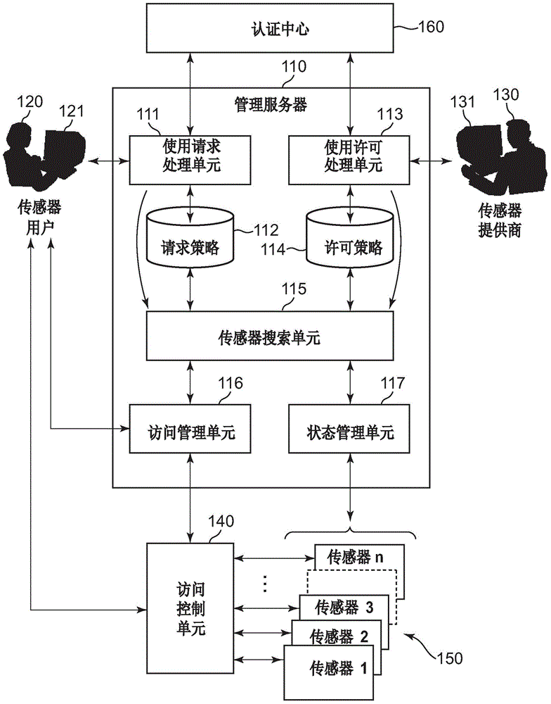
[0056] figure 1 is a block diagram showing the configuration of the management server 110 according to the first embodiment of the present disclosure. The general process is as follows: when the sensor user 120 sends a request for using a sensor to the sensor use request processing unit 111, it searches the sensors 150 provided by one or more sensor providers to find a sensor that matches the request, and the sensor user terminal 121 uses The discovered sensors are operational.

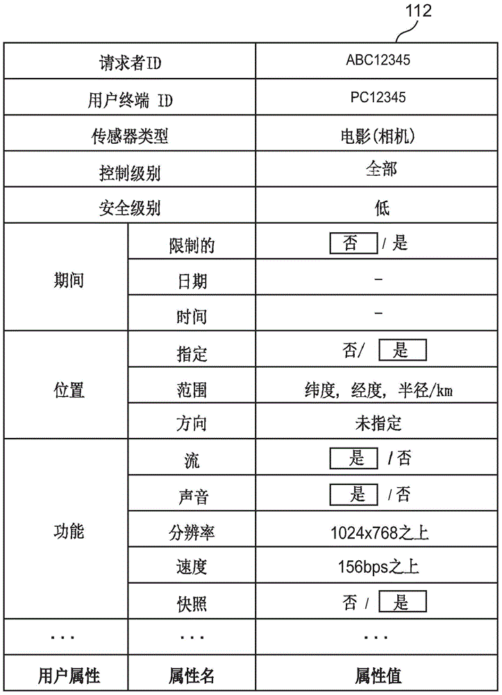
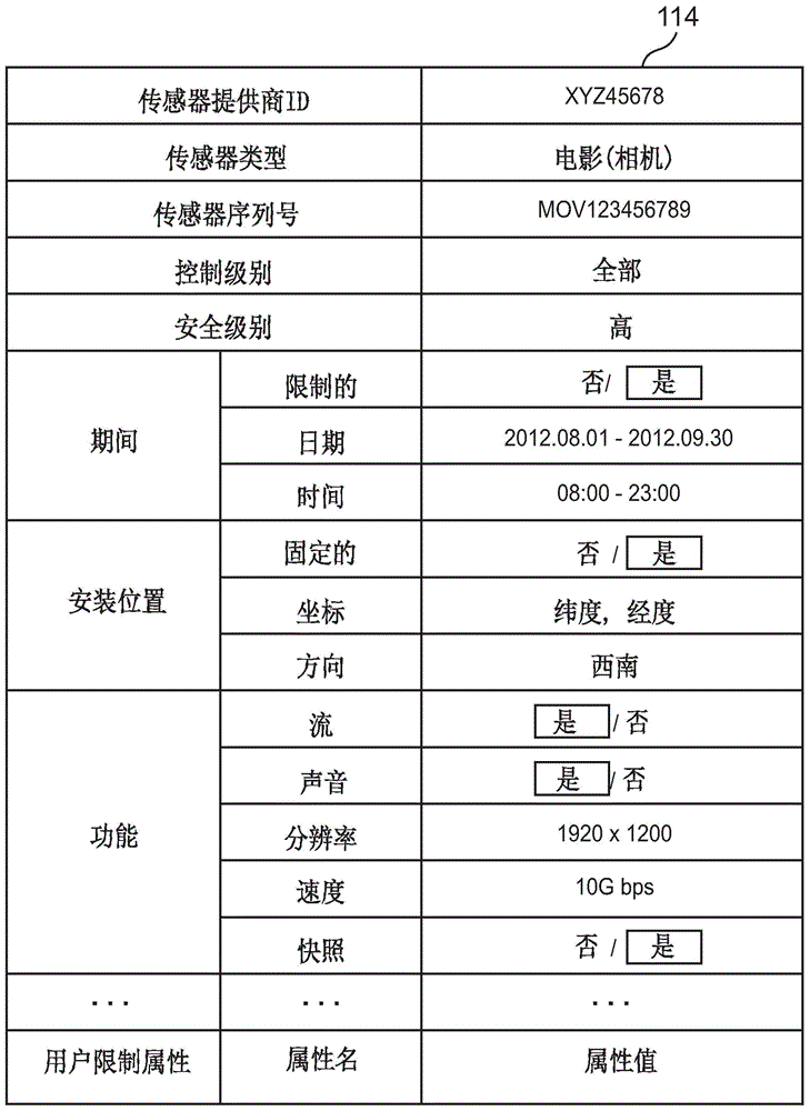
[0057] The management server 110 includes: a use request processing unit 111 that receives a request from a user; a request policy DB 112 that records a request policy; a use permission processing unit 113 that performs sensor registration provided by a sensor provider 130; a policy database 114; a sensor search unit 115 that performs matching between request policies and permission policies to find available sensors; an access management unit 116 that provides discovered sensors to users; and a sta...

no. 2 example

[0113] Figure 16 is a block diagram showing the configuration of the second embodiment of the present disclosure. The configuration of the second embodiment is the same as that of the first embodiment except that a GUI 330 is added to the sensor user terminal 121, and GPS 310 and GPS 320 are used to measure the position in real time. GPS 310 and GPS 320 enable real-time sensor sharing control when one or both of user terminal 121 and sensor 150 are moving.

[0114] In request policy 112, user attributes (user terminal) and their attribute values ​​(coordinates of the terminal) are also input. The location information of the user terminal 121 is periodically transmitted based on information from a GPS or similar device. The use request processing unit 111 receives the location information, and updates the coordinates of the terminal in the request policy 112 . In addition, the status management unit 117 periodically updates the coordinates of the sensors based on position i...


PUM


Abstract

The purpose of the present invention is to provide a sensor share control device and method for dynamically matching the policies of a sensor user and a sensor provider. In order to achieve this purpose, as a first embodiment, provided is a sensor share control device characterized by the following: a means in which a use request processing unit receives sensor use request information from a sensor user terminal; a means in which the use request processing unit records a use request to a requested policy, and the recording of the requested policy is communicated to a sensor search unit; a means in which a use permission processing unit receives sensor use permission information from a sensor provider terminal; a means in which the use permission processing unit records use permission to a permission policy, and the recording of the permission policy is communicated to a sensor search unit; a means in which the sensor search unit searches for a permission policy matching the requested policy in response to communication reception of the recording of the requested policy or the permission policy; a means in which a list of sensors included in the matched permission policy is created and sent to sensor user terminals that were recorded to the requested policy; and the means for searching in which searching is performed again dynamically if the requested policy or the permission policy are changed.

Description

technical field [0001] The present disclosure relates to a sensor sharing control method, and in particular, to a sensor control device, method and computer program product provided for multiple sensor providers and multiple sensor users. Background technique [0002] Recently, security cameras, motion sensors, etc. have been installed anywhere in urban areas, and mobile terminals can also be used as sensors. Car cameras have also been activated. What is needed is a method and device that can flexibly share, control, and use many of these sensors. [0003] Patent Documents 1 to 3 disclose specialized real-time information collection systems in which sensor providers register authorization policies and sensors owned by suppliers in a management system, and users register usage conditions and sensor functions that users want to connect to in the system; management system comparison Status of endpoints, usage requests, and authorization policies. However, the system does not...

Claims


Application Information

Patent Timeline
Patent Type & Authority Applications(China)
IPC IPC(8): G06F21/62
CPCG06F21/6245G06F21/6218H04L63/20H04L63/10
Inventor 津村直史盐谷知宏桐山隼人
Owner IBM CORP
Why Eureka
Try Eureka