Multilevel gas-liquid two-phase separation device

A phase separation and secondary separation technology, applied in separation methods, liquid degassing, chemical instruments and methods, etc., can solve problems such as experimental result errors, insufficient gas-liquid separation, and inability to collect carbon dioxide gas completely, and ensure accurate degree, good effect

Inactive Publication Date: 2015-06-10
大庆航天三沃新技术产业有限责任公司
View PDF5 Cites 2 Cited by
  • Summary
  • Abstract
  • Description
  • Claims
  • Application Information

AI Technical Summary

Problems solved by technology

[0004] The purpose of the present invention is to provide a multi-stage gas-liquid two-phase separation device to solve the problem of insufficient gas-liquid separation and incomplete collection of carbon dioxide gas in the existing physical simulation experiment of carbon dioxide flooding, resulting in errors in the experimental results

Method used


Image

  • Multilevel gas-liquid two-phase separation device
  • Multilevel gas-liquid two-phase separation device
  • Multilevel gas-liquid two-phase separation device

Examples


Embodiment Construction

[0016] Below in conjunction with accompanying drawing, the present invention will be further described:

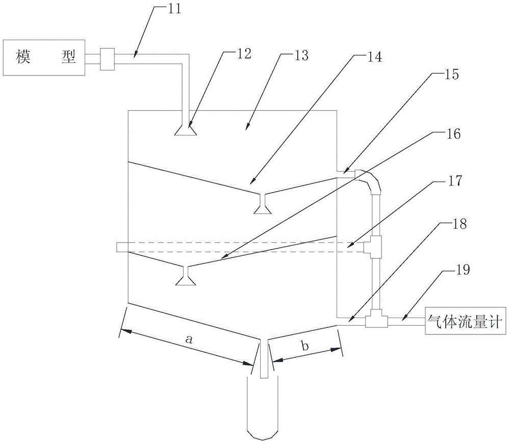
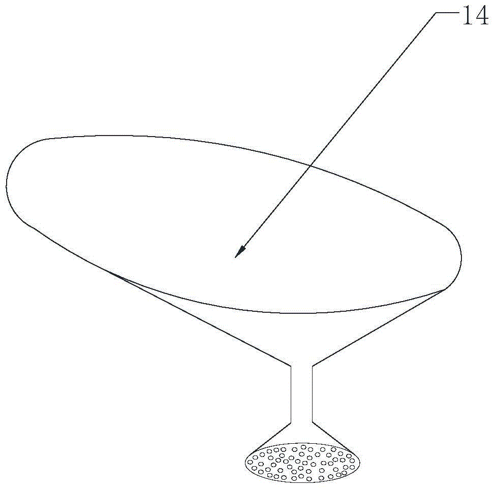
[0017] Depend on figure 2 combine image 3 Shown: a multi-stage gas-liquid two-phase separation device, including a cylinder 13, a mixed liquid inlet pipe 11 and a gas collecting pipe 19, the cylinder 13 is composed of a cylinder and a bottom, wherein the cylinder is cylindrical or elliptical Cylindrical, the bottom adopts an eccentric funnel structure, and the upper mouth of the funnel is a slanted mouth with a high left side and a low right side. The outlet of the cylinder is also located on the right side of the center line of the cylinder 13, so the left side of the bottom of the cylinder 13 The inclined wall a is longer than the right inclined wall b; the mixed liquid inlet pipe 11 extends into the cylinder from the top of the cylinder body 13, and the outlet of the mixed liquid inlet pipe 11 is provided with a primary separation screen 12, and the primary separati...


PUM


Abstract

The invention discloses a multilevel gas-liquid two-phase separation device, which solves the problems in the existing separation device that gas-liquid separation is not thorough and carbon dioxide cannot be collected completely. Three-level separation technology is adopted by the separation device, wherein a first-level separation sieve adopts a nozzle-type structure for sieving, and a second-level separation sieve and a third-level separation sieve both adopt an eccentric funnel-type structure, so that a gas-liquid mixture can be separated as long as possible on an area as large as possible, the gas-liquid mixture is fully separated, a good separation effect is achieved, meanwhile, a three-level collection mode is adopted, gas after each level of separation is collected, and separated gas is completely collected, so that guarantee is provided for carbon dioxide drive physical simulation experiment.

Description

technical field [0001] The invention relates to a gas-liquid separation device for a physical simulation experiment of carbon dioxide flooding. Background technique [0002] In the physical simulation experiment of carbon dioxide flooding, gas-liquid separation and accurate metering are the key steps to determine the quantification of oil displacement effect, so whether the gas-liquid separation and gas collection are complete is particularly important. [0003] The original gas-liquid separation device is attached figure 1 As shown, it is composed of a mixed liquid inlet pipe 1, a gas-liquid separator cylinder 2, and a gas collecting pipe 3. The mixed liquid inlet pipe 1 and the gas collecting pipe 3 are located at the upper part of the cylinder, and the main body of the gas-liquid separator cylinder 2 It is a cylindrical structure with an eccentric funnel structure at the bottom for liquid collection; the gas-liquid mixture generated by the oil displacement model flows in...

Claims


Application Information

Patent Timeline
Patent Type & Authority Applications(China)
IPC IPC(8): B01D19/00
Inventor 王海峰宋彬郭建刘志军
Owner 大庆航天三沃新技术产业有限责任公司
Why Eureka
Try Eureka