Stirrer for feed production

The technology of agitator and feed is applied in the field of feed production equipment, which can solve the problems of wasting electric energy, time-consuming and laborious cleaning, and increasing the work load of the motor.

Inactive Publication Date: 2015-06-10
浙江东立绿源科技股份有限公司
View PDF5 Cites 14 Cited by
  • Summary
  • Abstract
  • Description
  • Claims
  • Application Information

AI Technical Summary

Problems solved by technology

[0004] When the spiral stirring device is stirring, it will generate heat, and the stirred material will stick to the spiral stirring blade, which will undoubtedly increase the working load of the motor and w

Method used


Image

  • Stirrer for feed production
  • Stirrer for feed production

Examples


Embodiment 1

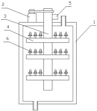
[0021] This embodiment includes a housing 1, a stirring device and a motor 2, the motor 2 is installed on the housing 1, the top of the housing 1 is provided with a feed port, and the bottom of the housing is provided with a discharge port, and the stirring device includes a stirring Shaft 3, stirring rod 4 and air pump 5, described stirring rod 4 is vertically fixed on the stirring shaft 3, and described air pump 5 is fixed on the housing 1, and described stirring shaft 3 and stirring rod 4 are hollow structures, and described air pump 5 communicates with the hollow structure of the stirring shaft 3, the hollow structure of the stirring rod 4 communicates with the hollow structure of the stirring shaft 3, the stirring rod 4 is provided with an air outlet, and the air outlet communicates with the hollow structure of the stirring rod 4. In this embodiment, both the stirring shaft and the stirring rod are set as a hollow structure, and the air pump supplies air to the hollow stru...

Embodiment 2

[0023] This embodiment includes a housing 1, a stirring device and a motor 2, the motor 2 is installed on the housing 1, the top of the housing 1 is provided with a feed port, and the bottom of the housing is provided with a discharge port, and the stirring device includes a stirring Shaft 3, stirring rod 4 and air pump 5, described stirring rod 4 is vertically fixed on the stirring shaft 3, and described air pump 5 is fixed on the housing 1, and described stirring shaft 3 and stirring rod 4 are hollow structures, and described air pump 5 communicates with the hollow structure of the stirring shaft 3, the hollow structure of the stirring rod 4 communicates with the hollow structure of the stirring shaft 3, the stirring rod 4 is provided with an air outlet, and the air outlet communicates with the hollow structure of the stirring rod 4. There are many stirring rods 4, which are fixed on the stirring shaft 3 from top to bottom. There are multiple air outlets on the stirring rods ...

Embodiment 3

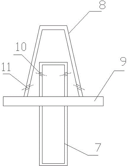
[0025] This embodiment includes a housing 1, a stirring device and a motor 2, the motor 2 is installed on the housing 1, the top of the housing 1 is provided with a feed port, and the bottom of the housing is provided with a discharge port, and the stirring device includes a stirring Shaft 3, stirring rod 4 and air pump 5, described stirring rod 4 is vertically fixed on the stirring shaft 3, and described air pump 5 is fixed on the housing 1, and described stirring shaft 3 and stirring rod 4 are hollow structures, and described air pump 5 communicates with the hollow structure of the stirring shaft 3, the hollow structure of the stirring rod 4 communicates with the hollow structure of the stirring shaft 3, the stirring rod 4 is provided with an air outlet, and the air outlet communicates with the hollow structure of the stirring rod 4. A blowing pipe 6 is fixed on the air outlet, and the blowing pipe 6 includes an inner pipe 7, an outer pipe 8 and an outer pipe fixing platform ...


PUM


Abstract

The invention discloses a stirrer for feed production. The stirrer comprises a shell, a stirring device and a motor, wherein the motor is mounted on the shell; a material inlet is formed in the top of the shell; a material outlet is formed in the bottom of the shell; the stirring device comprises a stirring shaft, a stirring stick and an air pump; the stirring stick is perpendicularly fixed on the stirring shaft; the air pump is fixed on the stirring shaft; the stirring shaft and the stirring stick adopt hollow structures; the hollow structures of the air pump and the stirring shaft are communicated; the hollow structure of the stirring stick is communicated with the hollow structure of the stirring shaft; an air outlet is formed in the stirring stick and is communicated with the hollow structure of the stirring stick; the stirring shaft is connected with an output shaft of the motor and is positioned in the shell. During stirring, stirred substances cannot be stuck to the stirring stick, so that extra work load of the motor cannot be increased, loss of electric energy is reduced, the stirring stick is not needed to be cleaned, and the labor is saved.

Description

technical field [0001] The invention relates to a feed production equipment, in particular to a stirrer used in feed production. Background technique [0002] The agitator is a commonly used equipment in the production of feed. Its function is to stir and mix the various components of the production feed together, and to mix each component evenly. [0003] The authorized announcement number is CN203540423U, and the authorized announcement date is April 16, 2014. The Chinese invention patent discloses a spiral mixer for feed production, including a shell, a spiral stirring device and a motor. The shell is cylindrical , a cylindrical vertical arrangement, a funnel-shaped outlet at its lower end, a cover plate at its upper end, and a feed inlet on the cover plate: the spiral stirring device consists of an inner spiral stirring blade, an outer spiral stirring blade Composed of the blade shaft, the external helical stirring blade is set vertically in the opposite direction to th...

Claims


Application Information

Patent Timeline
IPC IPC(8): B01F13/10A23N17/00
Inventor 徐新年吴建新
Owner 浙江东立绿源科技股份有限公司
Why Eureka
Try Eureka